Hall effect speedometer is reading 99+mph and glitching

speedbiker

1 mW
Joined
Sep 4, 2023
Messages
15
Location
Boston
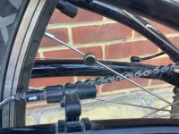
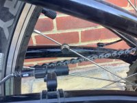
Hello, i have a phaserunner v6 controller, cycleanalyst v3 display, and the hall sensor on my back wheel isn't reading correctly. This happens occasionally when the magnet gets pushed out of alignment, and i just have to push it back into place, and i see the led blink on the sensor indicating it senses the magnet. But this time, when i push the magnet in place, no LED, and still the 100+ MPH glitch on the display. Also, the throttle doesn't work properly because of the error in the speed reading (some speed limiting thing glitching out).

Anyone know what to do?
 
This happened to me today on my BBSHD. The magnet has gone weak so I tried it using a brand new neodymium magnet popped on top of the old one. And it worked perfectly until it flew off at full speed when I was testing it my back garden, never to be seen again. I didn’t have my hot glue gun with me at the time, so before I lose the next magnet I’m going to hot glue it in place prior to testing it again.

Weak magnet
0DED9C65-ED86-44C4-96CA-A0BAA3D08B56.jpeg

Strong magnet
28F1DB1F-145D-4DEF-915C-0F805ED86420.jpeg
 
Last edited:
Hi, I have tried some other magnets but I don’t have any really strong ones. But I can see the original one still works by testing it with the other magnets. Still the LED on the sensor is always off, and MPH reads 0.00 even if I push the magnets right on the sensor

What should I do next? Is there a way to disable the speedometer temporarily till I fix it so I can ride without the throttle bugging?
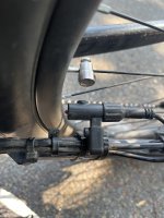
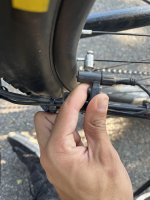
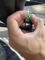
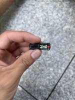
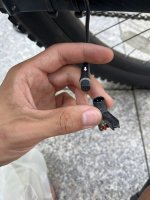
image.jpgimage.jpgimage.jpg
 
Most of these external wheel speed sensors use a reed switch (very few use a hall, which requires three wires to it instead of just two like the reeds), and like any other mechanical switch they have a finite lifespan...and they are made of glass so they can also be damaged from sufficient vibration or impact on the sensor stick body.

If it actually is a hall sensor, make sure it's actually getting 5v from the CA. If it doesn't, it won't operate.

The sensor is not always glued in place inside the housing, and the cable can twist the body inside and cause misalignment you can't see. Or back out of hte housing enough to make the alignment mark on the housing no longer aligned to the sensor inside.

The other thing that happens is the solder connections to the sensor inside the housing break, or corrode, or the wire breaks inside the insulation usually at the exit of the housing where it hangs off (or wherever it is unsupported or pulled or bent sharply).

Occasionally it's a problem further up the wiring, like at the JST at the back of the CA itself, etc.


If your sensor connects to the PR first, and then that passes the sensor data to the CA, then it's an even more complex wiring and connection path you need to check.


None of these should cause the speed reading on the CA to do anything other than show zero, unless there is an intermittent connection on the signal line that unloads the line and makes it like an antenna, and allows other RF / signal noise to enter the CA's speedo signal line.


If you can't fix the issue mechanically or electrically you can use the onscreen menus of the CA to effectively disable speed limiting here by setting the limit higher than whatever the glitch is:
Just make sure you take pics of the screens before you change anything so you can put them back later.
 
I opened it up, it’s glued in hard epoxy so I can’t figure out how to open it any more. But it does unplug, and I see 3 connectors so is it a hall sensor? Also, the cable connecting to the sensor goes to the motor btw.
I don’t have a multimeter right now to check the 5v
image.jpgimage.jpg
 
You can scrape a bit of that laquer off the pins and check for 5 volts. And if that’s ok try a new magnet. If you are in the UK then Halfords sell replacements for £1.50, but I’m going to glue my strong magnet on the top of the old one to see how long it lasts before falling off.

I previously bought 10 neo magnets off eBay for around £3.50 and hot glued a couple of them to my brake levers, but they aren’t spinning around at 35 mph.
 
Last edited:
To get a multimeter I need to get home so if anyone knows how to make the throttle work with the broken hall sensor

I tried changing the cycle analyst top speed to 600mph and same problem, even at max throttle only max 1000 watts are used out of 5000, and throttle cuts out weirdly
 
I opened it up, it’s glued in hard epoxy so I can’t figure out how to open it any more. But it does unplug, and I see 3 connectors so is it a hall sensor?
I don’t have a multimeter right now to check the 5v

Don't need to open it further, it's pretty certainly a hall based on what I can see of the insides. But you do need to see if it gets 5v at that connector. If it doesn't, it wont' operate, and you would need to find out why it isn't getting 5v (wherever it's coming from, if it is supplying it to the cable, if there is a cable fault, etc).

Also, the cable connecting to the sensor goes to the motor btw.
To the *motor*, or to the *controller*?

Wouldn't make any sense to go to the motor, since the motor doesn't read sensors.

But the Phaserunner has an option to pass a speed signal thru from an external sensor, so it could still make sense to go the controller.

If it actually goes to the *motor*, you're going to have to trace all of the wiring from the sensor all the way back to the CA, thru the insides of each thing it goes thru, to find out where the 5v, signal, and ground are being stopped, if you find it's a cable / signal / power problem. (which you will need a multimeter / voltmeter to test).
 
To get a multimeter I need to get home so if anyone knows how to make the throttle work with the broken hall sensor

I tried changing the cycle analyst top speed to 600mph and same problem, even at max throttle only max 1000 watts are used out of 5000, and throttle cuts out weirdly

You could try just grounding the signal line so that it can't glitch, but you need a voltmeter to find out which is the 5v line as you do not want to short that one out by accident.

Alternately, find the speedo plug on the back of the CA and disconnect it, if it's wired to it using a separate cable. It probably is not, so you probably can't do that--it almost certainly is wired into the CA via the main multipin plug to the PR. To disconnect the speedo signal from that, you'd have to open the CA and cut the speedo wire from the PCB (which you would then have to re-solder later).

If changing the CA's speed menu settings to max doesn't fix the problem, this means it is seeing noise on the speed signal line that is enough to read higher than that max (even if it doesn't show you that on the readout, which I would consider a bug in the CA software but it's probably been there a long time so unlikely to be changed). You may be able to set the CA's speedometer menu to a high number of poles and a different wheel size to change the speed reading that results from the excessive pulses being detected, which might put it below the limit again.

Or it means that the speed signal is going to the PR and the PR itself is programmed internally to respond to it by limiting the system, and that you need a computer, USB-serial cable, and the PR setup suite to change, and time to learn about it and experiment with the settings (and to backup all the existing settings to put it back once the hardware is fixed).
 
I measured the.3 lines with multimeter, 2 are 5v 1 is ground i guess
I tried grounding one then the other, both times, it just disabled the throttle.

I’m ordering a new speed sensor, but does the 2 5v lines mean something else is broken?

How do I get it riding without the throttle bugging bc of speedometer glitch?

You could try just grounding the signal line so that it can't glitch, but you need a voltmeter to find out which is the 5v line as you do not want to short that one out by accident.
Alternately, find the speedo plug on the back of the CA and disconnect it, if it's wired to it using a separate cable. It probably is not, so you probably can't do that--it almost certainly is wired into the CA via the main multipin plug to the PR. To disconnect the speedo signal from that, you'd have to open the CA and cut the speedo wire from the PCB (which you would then have to re-solder later).

If changing the CA's speed menu settings to max doesn't fix the problem, this means it is seeing noise on the speed signal line that is enough to read higher than that max (even if it doesn't show you that on the readout, which I would consider a bug in the CA software but it's probably been there a long time so unlikely to be changed). You may be able to set the CA's speedometer menu to a high number of poles and a different wheel size to change the speed reading that results from the excessive pulses being detected, which might put it below the limit again.

Or it means that the speed signal is going to the PR and the PR itself is programmed internally to respond to it by limiting the system, and that you need a computer, USB-serial cable, and the PR setup suite to change, and time to learn about it and experiment with the settings (and to backup all the existing settings to put it back once the hardware is fixed).
 
Back
Top