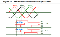
I am referring to the ST document about motor control, it is too complicated a subject to understand and remember. I am trying to understand the hall electrical phase shift as shown below

My understanding of the importance of the phase shift parameter is below, please correct me if i am wrong
The first position as below is the rotor 0 Degree.

When BemfA is at peak it is at 90Deg, the vector sum of all the Bemf is at 90 degree to the rotor position. The Iq shall overlap with the resultant Bemf vector for Max torque. I shall drive my FOC in such a manner. Is it correct? Few clarifications are the Bemf is phase voltage or line voltage i have to consider? What changes i have to make if i consider only line voltage BEMF since the neutral is not available? Can the delay be any angle like 60Deg etc? Please help.
ST document page 94.

My understanding of the importance of the phase shift parameter is below, please correct me if i am wrong
The first position as below is the rotor 0 Degree.
When BemfA is at peak it is at 90Deg, the vector sum of all the Bemf is at 90 degree to the rotor position. The Iq shall overlap with the resultant Bemf vector for Max torque. I shall drive my FOC in such a manner. Is it correct? Few clarifications are the Bemf is phase voltage or line voltage i have to consider? What changes i have to make if i consider only line voltage BEMF since the neutral is not available? Can the delay be any angle like 60Deg etc? Please help.
ST document page 94.

