Hi e-bikers
I am looking for some suggestions on trouble shooting my e-bike problem. Last week on the way home the motor started sputtering. Didn't start smoothly and when it ran, it was noisy at low rpms. At this point it does not start up anymore at all. However, I can _sometimes_ get it going by starting it forward by hand (at some significant speed). It will run ok, although it seems a little less smooth than normal. It doesn't reliable run like this though. Turning off power and restarting improves the odds of it running like this.
My guess is always Hall sensor connectors. I have two sets of connectors - my controller (situated in bike front panier) to the wiring attached to frame, then a set near the rear hub (an Ezee geared motor, which I think I got from Grin Tech). After suffering lots of problems with the single row amphenol connectors (corrosion), i replaced the rear set with a 5 pin mini-XLR two years back. The phase wiring is Anderson power pole. Near the controller I still have the flat 5 pin connectors for Hall and bullet connectors for power. I am convinced the connectors are good this time.
Next guess: Hall sensors. Got out my multi-meter and probed the back of the connector of the controller cable i.e. as close to the controller as I can get. I am still not sure why, but initially I got a strange reading 5 V every where. That was Friday morning before work. Confusing. On the way home, I picked up a new set of Hall sensors at Grin just in case and also brought a scope home.
I made the mistake disconnecting the Hall sensors at the controller and trying to measure the Hall sensors by supplying 5V from a USB power supply and measuring the 3 signals (wrt to gnd) by spinning the wheel backwards (yes, it's geared after all). That is a mistake because after checking the specs for some Honeywell hall sensors I realized they probably have open collector outputs. This means you have to connect them to your controller to see the 5 V pulse. Internally (i think) the controller has a weak pull up to 5 V. The Hall sensors either ground the signal (when output transistor is on) or let it sit a 5V (transistor off). The signals then probably go into a comparator. Feel free to correct me.
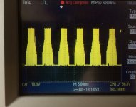
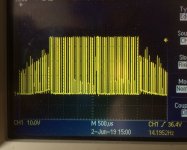
So with better leads attached to the back of the controller connector, I see nice 5 V pulse trains on all 3 hall wires. I have two probes for the scope and can see them out of phase, each 50% duty cycle. The fact that they are open collector and that I am seeing the signals ALSO means they are indeed pulled to 5 V in the controller and there cannot be a problem with the wiring from the PCB to the connector I am probing. Right ?
Oh - my throttle seems to produce 0.2 --> 4.3 V as I press it, so thats seems ok. Plus a throttle issue doesn't really explain sputtering and start up problems.
So now I am stumped. What is next ? I am suspicious of the controller but i am not sure what to test next. Could it be a motor issue despite healthy looking Hall signal ? Anything else I should check on the motor side ?
Any suggestions are greatly appreciated. I need this thing for my daily commute.
Gertjan
I am looking for some suggestions on trouble shooting my e-bike problem. Last week on the way home the motor started sputtering. Didn't start smoothly and when it ran, it was noisy at low rpms. At this point it does not start up anymore at all. However, I can _sometimes_ get it going by starting it forward by hand (at some significant speed). It will run ok, although it seems a little less smooth than normal. It doesn't reliable run like this though. Turning off power and restarting improves the odds of it running like this.
My guess is always Hall sensor connectors. I have two sets of connectors - my controller (situated in bike front panier) to the wiring attached to frame, then a set near the rear hub (an Ezee geared motor, which I think I got from Grin Tech). After suffering lots of problems with the single row amphenol connectors (corrosion), i replaced the rear set with a 5 pin mini-XLR two years back. The phase wiring is Anderson power pole. Near the controller I still have the flat 5 pin connectors for Hall and bullet connectors for power. I am convinced the connectors are good this time.
Next guess: Hall sensors. Got out my multi-meter and probed the back of the connector of the controller cable i.e. as close to the controller as I can get. I am still not sure why, but initially I got a strange reading 5 V every where. That was Friday morning before work. Confusing. On the way home, I picked up a new set of Hall sensors at Grin just in case and also brought a scope home.
I made the mistake disconnecting the Hall sensors at the controller and trying to measure the Hall sensors by supplying 5V from a USB power supply and measuring the 3 signals (wrt to gnd) by spinning the wheel backwards (yes, it's geared after all). That is a mistake because after checking the specs for some Honeywell hall sensors I realized they probably have open collector outputs. This means you have to connect them to your controller to see the 5 V pulse. Internally (i think) the controller has a weak pull up to 5 V. The Hall sensors either ground the signal (when output transistor is on) or let it sit a 5V (transistor off). The signals then probably go into a comparator. Feel free to correct me.
So with better leads attached to the back of the controller connector, I see nice 5 V pulse trains on all 3 hall wires. I have two probes for the scope and can see them out of phase, each 50% duty cycle. The fact that they are open collector and that I am seeing the signals ALSO means they are indeed pulled to 5 V in the controller and there cannot be a problem with the wiring from the PCB to the connector I am probing. Right ?
Oh - my throttle seems to produce 0.2 --> 4.3 V as I press it, so thats seems ok. Plus a throttle issue doesn't really explain sputtering and start up problems.
So now I am stumped. What is next ? I am suspicious of the controller but i am not sure what to test next. Could it be a motor issue despite healthy looking Hall signal ? Anything else I should check on the motor side ?
Any suggestions are greatly appreciated. I need this thing for my daily commute.
Gertjan