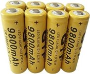
Thanks for the reminder, (I'm a bit of a hoarder) but today put 15 pouch cells in salt water (as A W tip to quich discharge them) they will then go in the battery recycling. It's a start but I have a lot to sort. On that many of the ones I was reluctant to immediately recycle are still in pairs (cos of the PCB), as a pair they are charging but not good enough. I was thinking of using my dremel to seperate them and test them individually in case one is good and the other parasitic. Do you think its worth the effort?It seems to be Frozen or maybe lost its threads I don't know why some of these disappear but he has a lot of good information dark Angel.
Hopefully a moderator can chime in and help as I didn't understand why I couldn't pick up his old threads?
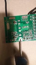
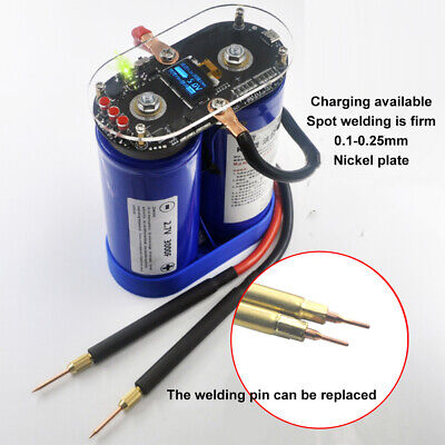
Plus I'm looking at battery spot welders maybe you can start a thread on your spot welder and how you got it to work so well I see some blue to capacitor spot welders for under $90 able to weld 03 pure nickel.
Have you gotten rid of the batteries that are old or unusable ?
All the ones I consider "Known to be good" are also in pairs, but getting great results and consistent results from each pair, still a lot to go thru tho, so for now assumed both must be good def worth keeping.
On trying some of the 36v pouch batteries that looked good and had held full voltage for ages (over a year), so tested them straight on the bike. The batteries did will, so far only got thru 3, all working at least ok. would have got further on that but the bike had some issues, like a flat tyre, and front break would not release, and some bad connections in a box on the handlebars (manufacturer fitted) and a switch broke, All fixed now, ex the switch which is on order. Shorted out n taped the wires for now.
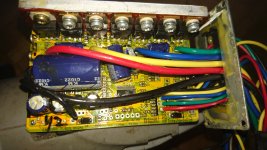
Feel free to ask anything you like about my experience with the spot welder I bought. Nice to be able to give something back, you been v helpful. Not saying this is the best or of professional quality, don't know how it will last in the long term, but it is quick and has not struggled so far, doing just one after another, (I stop every now and then to check the battery voltages but so far they are both on their first charge still, probably being over cautious. For the price, I think its great, and not the end of the world if you decide to get a better one later, at that price still a good spare one (least I think). Looking on e-bay it looks very like you can now get even cheaper versions for as little as £10, I cannot comment on them, as I have not used one.
But it looks like a bigger Chinese company has simply decided to rip the idea of from the smaller Chinese company and made them even cheaper still. But that bit you would have to determine yourself. they might not be as good. But I would imagine there will be reviews on you tube of people who have bought them and tried them, that was the main research I did when buying mine.
Keith
Keith
")