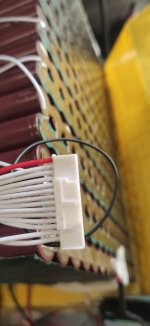
Okay. This is your work. I've numbered the cell pins with the right B labels. B0 should be the black wire on the BMS cable. I don't understand your voltage data.
Put the black probe on your meter on B0. This is what you should get, B2 will be 4V, B4 will be 12 V, B6 will be 20v. etc, all these even pins increasing 8V per pin. B20 to B0 is the full battery voltage of 80V.
View attachment 335532
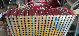
And the other side should be wired like this, If you keep the black probe of your meter on B0, B1 will be 4 volts and as you move left to B19, B3 will be 12 volts and the others will increase about 8volts per pin.
View attachment 335535
If you wish to see individual group voltages, and this should be obvious, you probe the opposite sides of the battery. For example, the first group #1 is checked at B1 and B0, Group 2 checked at B2 and B1. Do all 20 groups.
Don't have to remind you to be careful, All of the banks are at full charge, and there's 80-84 volts sitting here, Make sure no metal can touch those exposed nickel ends.