Sensors mystery - HELP

Smurf2

100 W
Joined
Jun 25, 2022
Messages
158
Hi. This is my second brake sensors bought because I thought that first maybe won't work.

I upgraded to KT controller. 48v battery. More about this upgraded here.

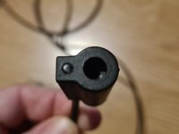
The way which sensor working is that activate when you hang it to one side (where arrow show). The ball touch some conntact inside and red light must apear.

I found that 3 wires from both side have 6 combinations, right? So I tried and soldered them 18 times (all combinations x 3), with different connectors, and not working. Even didn't got a red led light!

But, the biggest mistery is next:
Test sensor on 1 lithium battery on 3.80v show me red light.
But, what the hell I can't got red light when 2 wires connected on 3pin julet connector from BUS cable ??? There is a 4.6 volts from that connector!!

If 2 wires of sensor works on battery 3.80v, must work on wires from BUS. I checked many combinations with 2 wires and not got red light! How is that possible?

Also other strange thing is, when connect 2 wires from sensor and two from BUS, turn main bike battery, and check voltage, and it gives me only 1.4volts! Is that must be like that? That is maybe reason why not got red light, because when you connect sensor, it looks like eating all power.

But this sensor is made for 5-24v.

Connection from julet connectors is good, and my old sensor (with magnet) works fine.

I cut and shorten sensor wires, not help.
20240217_201455.jpg
20240113_142332.jpg
20240218_110331.jpg
20240218_105434.jpg
 

Attachments

  • 20240216_180929.jpg
    20240216_180929.jpg
    320.7 KB · Views: 3
Last edited:
I believe you did it wrong. Connect red-red, black-black, and white to blue.

Red and Black are power. Blue/White are for the signal from the Hall chip inside the sensor.

When you do random connections, you can put power backwards into the Hall sensor and damage it, or you can short circuit the controller's 5V power supply.

smurfer.jpg
 
I believe you did it wrong. Connect red-red, black-black, and white to blue.

Red and Black are power. Blue/White are for the signal from the Hall chip inside the sensor.

When you do random connections, you can put power backwards into the Hall sensor and damage it, or you can short circuit the controller's 5V power supply.
On that picture is just 1 of 6 combinations which I tried!
In this case, red is positive and blue is negative here on upper connector. Only that two wires give a voltage.

Stll not damage it. Red light works on battery, but not when connected to ebike.
 
Last edited:
These HWBS sensors in general use an output that when active just grounds your existing ebrake signal wire, and otherwise does not output a signal (it just floats to whatever voltage is attached to that signal wire) so that they can be compatible with various types of controllers and voltages. (similar to motor halls). They require a 5v nominal supply, usually, but depends on the specific sensor used--there are halls available that work from as low as 3.5v (sometimes less) all the way up to 30v.

Normally the active output voltage on the signal wire is around 0.8v. The inactive output voltage will be whatever your ebrake wire has on it; the sensors can usually handle up to 20-30v placed on that open-collector output, depending on the specific sensor used.

Physically there is a magnet in a channel with a spring holding it at one end of that channel, and a steel brake cable placed in the channel will attract the magnet so when the cable is pulled in the direction indicated on the HWBS unit, it will pull the magnet along the channel until it activates the sensor, grounding the output. Releasing the cable will let the magnet be pushed by the spring back to the neutral position, deactivating the sensor.

But, as noted by docw009, incorrect wiring can damage the sensor (like any other electronics), so if you've tried several wirings there's a strong possibility that it isn't going to work correctly anymore, or that it may work but have random wierd problems from now on.

The image in the ad indicates the wiring you should be using, so don't use any wiring other than that, or you risk damaging the parts. (this is generally true of any electronics--you want to be sure of what you're connecting to where *before* you connect it, and not just try different things out)
1708296221603.png

It's also possible that the units were defective or damaged before you ever got them; ali* and other sources like that can be a crapshoot for quality.
 
Last edited:
Oh, sorry guys. My bad. I should have asked on the forum first. I did not consider it so serious because there are only 5 volts there.

I many years buying electronics from AliExpress and can't remember of some issue. But 2 new pair of sensors of different sellers, no way that both faulty.

Ok, if you think that I damaged it, I have 1 left sensor which is intact, so I can try with it? But will be same. Red light will not light up, and when will place in outside battery, light will light up.

On picture, you see I have 2 different jacks. On one is Positive red, on other is white. Negative on one is blue, on other is black. On Post #1 you see multimeter which wires give voltage.

ZomboDroid_19022024083307.jpg
 
Your picture may indicate you've already done this, but if not:

To wire it up correctly without worry about potential damage, you need to know, for sure, what your controller's wiring on the ebrake connector is, for the 5v wire, the ground wire, and the signal wire.

Then you need to know, for sure, which wire on your "jack" adapter cable goes to which pin on that controller connector.

Then plug in the adapter into the controller connector, with it's bare wires separated so they can't touch.

Then verify with a multimeter set to 20VDC, with it's black lead to your battery negative, and measure the actual voltages you get on each of the bare wires, and note them down.

If the wires don't measure the right voltages for what's expected based on the signals you know they should be, then the wiring traced out and noted down before may be wrong, or the notes may be wrong.

You should have one that is the same 5V you can measure on the throttle connector that is the 5v power supply, another that is 0V that is ground, and a third that should be nearly 5v that is signal.

Manually grounding that signal wire to the 0V wire should engage the ebrake of your system. If it doesn't,

If you don't get those voltages, and/or grounding the signal wire doesn't engage your ebrake, I'd check first to be sure what you've got hooked up there, and that is indeed the correct ebrake connector of your controller. If your ebrake connector doesn't provide 5v power, you will have to splice wiring in from something else, like your throttle, or PAS sensor, to get power to the sensor.


Once you're sure of the controller side connections, then you can compare those with the wiring pinout for your sensors, and make sure you connect each of the wires for the sensor only to the matching wires on the jack.

If you want to make sure the sensor itself works correctly before hooking it up (and you can test the others too), then use an old / spare USB power adapter / charger that outputs 5v, and connect it's 5v to the sensor 5v, and it's ground to the sensor ground. Measure with voltmeter on 20VDC with it's black lead on ground and it's red lead on sensor signal. Engage the sensor with a bit of brake cable inside it, moving it each way, and see what the signal output voltages are for each, and what the red light on the sensor shows you.
 
On that picture is just 1 of 6 combinations which I tried!
In this case, red is positive and blue is negative here on upper connector. Only that two wires give a voltage.

Stll not damage it. Red light works on battery, but not when connected to ebike.
The blue is not the negative. The blue is the signal wire. When not connected, the pull down resistor in the controller pulls the voltage down to near 0v, so it looks like a ground when you take the measurement.
 
Thanks guys for detailed explanation. It seems that I exchange the word Ground with Negative (-), but that are different things.

Anyway, I solder wires like you said. Red to red, black to black, blue to white. To avoid misunderstanding, I take a picture of each wire so that you can check real voltage.

4.68v goes from the controller. But just 1.44v from red and black wires when Sensor is attached. It seems that value are not changeable when moving steel cable trough sensor. Also tried black and blue with moving cable, but it always show 0 volts.

I can mention that in one time, red light was barely visible in the dark, very low low visible. When shut off battery and turn it again, not see that light again. So, that's mean that only 1.44v going to the sensor? Test on lithium battery 4.6v red light is high illuminate, high visible to the eyes.

Also, I attached last brand-new sensor to confirm, and seems that is the same. Not see any difference.

20240220_221211.jpg

20240220_231151.jpg

20240220_230945.jpg

20240220_231058.jpg

20240220_230236.jpg

20240220_230025.jpg

20240221_004756.jpg
 
I see that what you've done is wire the brake sensor pins to a unused male 3 pin connector. Have you looked inside the extension cable to see what wires are used in the three pin female socket? The position of power, ground, and signal on the pins may not match the red, black, and blue on your three pin connector. It could be even worse ,,,,

I had a 4-n-1 harness last year for my KT controller. It had yellow three pin connectors for the brakes, but my brakes used the red two pin Julet connectors.. I cut the yellow three pin sockets ones off the harness to splice in a red connector, They only used two wires, signal and ground inside the cable, No power! I don't know about these 4-n-1 harnesses. They may all differ.

I think it would be worth looking inside the cable. If they only use two wires, the signal wire will have a pullup resistor to +5V on it, and look like a 5 volt signal. Then if you power the sensor off signal and ground, it might have a dim red light?
 
Think of the sensors as a simple Normally Open switch which closes when activated, so use the continuity setting on your meter to check the sensor output over the blue and black wires while supplying with 5v via black/red. could be blue and red but i think its probably grounding to activate the cut off.

edit.. mention of the white wire above threw me , edited to correct.
 
Last edited:
@docw009 that what I have is KT BUS 1t5. I had before 1t4, and now upgraded to KT. Maybe that is julet jack (with blue wire) from 1T4, can't check right now.

I already take a note of continuity from pins of booth jacks, and I will post it here later.
 
Last edited:
20240221_172735.jpg

pinout1T5_cable.jpg

Which use of this two Julet?
pinout2.jpg
pinout3.jpg


Ok. I made continuity test. On my 1T5 have 3-pin Male connectors. Don't know am I draw correct this time (first picture), but the two pins on the right only give voltage, so we call them Positive and Signal?

If we look other two julet Female
(White/Red/Black and Blue/Red/Black), we can see that all connections and color wires were wrong before.

Now, maybe the best use White/Red/Black Julet? Because it seems Positive wires are match (they are on the same side)? But looks that Ground/Signal maybe reversed?
 
Last edited:
If you have tried every which way, then the harness must not support your active brake switch. You should open the cable behind the 3 pin Julet to see if it really has three wires or just two wires for signal and ground.

Or you can do continuity tests to the 8 pin round connector on the end of the 4:1 harness.

Looking at the male pins on end of the 4:1 harness. It's a 8 pin connector, This is a safe test if the harness is not connected to anything. You're just measuring continuity from one end to the other.

....8 v 1
7...........2
6...........3
...5.....4

Pin 8 is ground and pin 1 is the brake sense
Pin 6 is +5V.
 
View attachment 347956

View attachment 347957

Which use of this two Julet?
View attachment 347958
View attachment 347959


Ok. I made continuity test. On my 1T5 have 3-pin Male connectors. Don't know am I draw correct this time (first picture), but the two pins on the right only give voltage, so we call them Positive and Signal?

If we look other two julet Female
(White/Red/Black and Blue/Red/Black), we can see that all connections and color wires were wrong before.

Now, maybe the best use White/Red/Black Julet? Because it seems Positive wires are match (they are on the same side)? But looks that Ground/Signal maybe reversed?
If face on representations of both male and female connections You will need to rotate one through 180 degrees through the vertical plane to mate them :) so one will appear be left to right in that context....

so this face on.
pinout2-jpg.347958

is a female match
for this face on

pinout1t5_cable-jpg.347957
 
Last edited:
Its hard to visually see the small, dark line over dark housing to line up the orientation slot.
 
1T5-9-PIN-CONTINUITY_3-PIN.jpg
20240127_153422.jpg
I have 1T5 cable with 9 pins.

I made continuity of Sensor 3-pin connector and 9-pin from other side.

I can't find any continuity on pin num. 1 on small (3-pin) connector. Is that have logic?

Also sending picture of cutted cable if need, when I was shortend it.
 
Last edited:
Does your controller have a label on the side? Usually that says how the ebrake is supposed to communicate. For example, here's one that says brake input low level:
61yy3zWovWL._AC_UF1000,1000_QL80_~2.jpg
For that you just need to ground the line. There's also high level, which is different.
 
Seems like the most common solution is to steal +5V off the throttle connection to power the hall sensor:
 
Does your controller have a label on the side? Usually that says how the ebrake is supposed to communicate. For example, here's one that says brake input low level:
View attachment 348009
For that you just need to ground the line. There's also high level, which is different.
When you said just ground the wire, I thought great! I will just put Ground wire to bike frame! :) But from last post, it seems that I need 5v from somewhere...

Can I try test with outside lithium battery, Positive join to red wire of sensor and other two (signal/ground) join normally? If yes, then negative from that battery must joined to that ground wires or?
ZomboDroid_23022024061200.jpg
 
Last edited:
You've confirmed that your harness only supports the signal and ground wire to the 3 pin julet. You can replace your brake sensors with the simple two wire magnetic contact type. I have those on several of my ebikes with hydraulic levers.

Or you can cut your harness and run 5 volts to the unconnected power pin from the throttle section. That will make for a messy harness and decrease its waterproofing and reliability,

Or run without brake cutoffs.
 
You can replace your brake sensors with the simple two wire magnetic contact type.
No. I using temporary sensor with magnet, which will fall out one day!
Or you can cut your harness
Already was cutt and closed.
and run 5 volts to the unconnected power pin from the throttle section. That will make for a messy harness and decrease its waterproofing and reliability,
I have already cutted pleace on throttle cable where was wires mixed, because connectors was different. So I can just add wire from there.

Can I try test from last Post?
 
sure you can try a low voltage test with a battery but if it fails retry using a 5v supply from a usb source? before writing off the sensor.
 
I can confirm, it works perfectly :)
Tested on 1S battery. Although sensor is intended from 5-24v, it works at only 2.8v (2xAAA), and maybe lower.

So, if I would still voltage from throttle, from joints of both connectors before, is about 10cm one from another. Hope that is ok.

I only need that one wire, no extra wire, like extra Ground, from throttle?

On throttle have +4.6v, -4.6v and +3.8v. Do I steel bigger voltage or lower voltage (signal)?

Would be stay enough for throttle?
 
Last edited:
Back
Top