DanGT86
100 kW
About 4 years ago I bought some 10Ah LiCoNiMnO pouch cells. I have kept them stored in a cool dry environment at about 3.7v. I pulled them out of storage and ran a discharge test with my Hyperion 1420 charger to see what kind of capacity and sag they had under load. Unfortunately the charger doesn't have the capability to produce anymore than a 1C load on these cells. It also only lets me discharge to 3v through the loaded discharge lead rather than the measurement at the cell tab. I was hoping somebody could help me make sense of the results I got from the test.
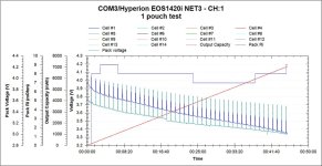
I used some less than ideal alligator clips on the cell tabs for the main discharge wires to the charger. I also used alligator clips directly on the cell tabs for the balance leads going to the charger. On the graph the Voltage of the main leads is shown in green and the voltage on the balance leads is shown in blue. The charger pulses off about every 30 sec so you have to ignore the spikes and just look at the basic discharge curve shape.
There is an obvious difference between the discharge lead voltage and the balance lead voltage measured at the cell tab. Which of these measurements should I be looking at?
Most cell tests I've seen only have one discharge curve at a specific current. These cells seem to be acceptable if I look at the measurement at the cell tab through the balance lead but they look pretty saggy if I go by the measurement at the main lead under load.
Test was a single pouch at 10A
I got about 7ah before the charger hit its 3v minimum cutoff voltage as measured through the main lead under 10amp load. I got about 2.5ah more by reducing the current to 1amp.
What do you guys think? Do I need to setup a better testing method? Are these worth the trouble of building a pack with or are they compromised from sitting for 4 years? Is this voltage sag acceptable to run 2C avg and 5c peaks?


