Help with 72v 1000w Controller Install.

Carguy7555

1 mW
Joined
Nov 17, 2016
Messages
10
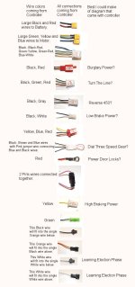
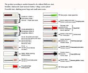
I just got a 72v 1000w controller and am having trouble figuring out the wiring. I attached images of the plugs and wire colors coming out of the controller and attached the supposed wiring diagram from the shipper. Not sure the wiring diagram they included is even for this controller. Looking at the images you can see I've already installed the XT60 plugs on the battery positive and negative terminals for the controller. And XT60's on the yellow, green and blue motor power wires. I understand those wires. My problem is, which are the throttle wires and I'm guessing wires have to be shorted to turn on the controller. At this point I would be happy having enough done just to see the wheel turn. I have a couple of different throttles. One has yellow, brown, green, white, black and red. Another has yellow, green, blue and red. Another has Red, white and black. I think I can use the red, white and black throttle as long as I know what wires need to be shorted to turn on the controller (like pushing the power button on the throttle). The motor hall sensor wire colors are black, blue, green, yellow and red. The controller hall sensor wires have 2 striped colors per wire shown in the attached image. There is a blurb in the paperwork from the shipper implying hall wires may not be needed with this controller. I would be willing to Paypal someone a consult fee if they could get me through this. First to get it spinning, then if you had knowledge of the accessory wires. Thanks in advance for your help. Rich
Controller1.jpgController2.jpg
 
What you got does not exactly match what they say it was. Amazing. :roll:

Connect small red to the battery +, and connect the big battery wires.

Connect the phases and the halls. Match the colors.

Connect the throttle

Connect the two learning wires to each other, the wheel should start spinning, so have it off the ground. Once it runs, disconnect the learning wires.

Now your bike should be running.

No idea what the other shit does. Once running see what happens with the other jumpers. I'd unplug them at first. One might be reverse.

You might have to jumper the burglary power too. that might be a second key switch loop.
 
I've got a 96V one similar to yours. You need to connect the power door lock cable to battery positive to turn the controller on. The one you have labeled Turn the line is the throttle connection. If you use the hall connector, it should just plug in. Then short the learning wires to get it running right. Then disconnect them. I run mine sensorless and it works great, but I haven't figured out how to get regen braking. Everything else works fine including both low brake and high brake. One of these days I'll probably open the controller again and see if I can get electronic braking working, but it's not a priority since it's not my everyday bike.
 
Wesnewell, Dogman dan, It's running. It was the small single red wire they had listed as "Power door locks" that had to be connected to +72v. I connected the throttle red, black, white to the controller red, black, green (they had marked as "turn the line"). I connected the white learning wires and pulled the rear tire off the ground (I'm glad you told me that or we would have had to buy new furniture). When I connected the power it started turning backwards. I hit the throttle once and it came to a stop and then started turning forward. I then disconnected the white learning wires and it seems to be working good. I'm not seeing a difference between having the hall sensors hooked up or not. But that's free spin and not under load. Boy, looking at the 48v free spin speed vhs 72v free spin speed, it was a scary fast free spin speed. It looks like it's time for leathers. I hope the loaded test goes as good as the free spin test now. Now I'm curious what the multiple other wires do that are unused. Thanks for your help getting it going. Wesnewell, you mentioned your low and high brake was working. What is that. And when you say "electronic brake" is that regenerative braking? If so I would like to get regenerative braking working also. Rich
 
Low brake just connects through the ebrake switches. High brake does the same but it connects to battery positive. They just shut power to the motor when you pull the brake handles. I'll have to open the controller and see if I can figure out electronic braking, but I may or may not do that anytime soon. AAnd probably not soon. But it is something I would want to do before making it my main ride. There;s 2 types of electronic braking, Regen which turns the motor into a generator, and then real braking which applies power to the motor to bring it to a complete stop. Regen braking usually cuts out below ~7 mph.
 
I understand that the brake wires cut out the motor when you hit the bikes mechanical brake. So it sounds like that's what the low brake does? If that's the case I'm not getting the high brake part yet. High brake connects to the battery positive to cut the motor out while mechanically breaking? Rich
 
On mine they both just cut power to the motor. Yours may be different. You also have a pair of pink wires I don't have. They could be for braking. I don't know. I don't have the yellow-green wire shown in the controller.jpg file you posted. I got the same jpg with my controller. The controller wiring just doesn't match it. On my old 72V controller, brake low engaged regen braking while brake-hi engaged real EABS braking. I had to adjust the LVC for them to work at voltages over ~78V. It's a damn shame you can't get good info from most of these vendors. Honestly I just don't think they know, and the language difference isn't a help. Here's info on the controller I use on my other bike.
https://endless-sphere.com/forums/viewtopic.php?f=2&t=29469
 
It is crazy the little to no info you get with a controller or complete system. I don't think I've ever bought anything with such little info included. And it's not like none is needed for these parts either. As competition gets greater in this area the ones with more documentation will get the greater sales. It's only a matter of time. We must just be early in the diy ebike arena. Rich
 
Carguy7555 said:
As competition gets greater in this area the ones with more documentation will get the greater sales.

You'd think so, but it really doesn't work out like that, or http://ebikes.ca would be billionaires by now. ;)

If you read around ES (and the rest of the web) you'll find that generally, people will buy the cheapest thing rather than the best thing, or even the best compromise, even after they've seen what happens to others that do that. :roll:


As for the wiring, there are a lot of threads that talk about wiring up controllers, if you have the time to poke around ES for them, that will give you info on how *those* controllers had to be hooked up to work, and what they had for labelling of various wires and functions (because they are not always labelled the same).

The functions may also not behave the same even if they are labelled the same. For example, I have "ebrakes" on different controllers that cause the following different behaviors:
--simple turn off motor power, no braking
--turn off motor power, and turn on regenerative braking that is proportional to speed (faster = more braking)
--turn off motor power and turn on regen braking that gets stronger the *slower* I go
--turn off motor power and turn on regen braking that starts out low but switches to stronger when I get below a certain speed
--turn off mtoor power and turn on regen braking that starts off strong but gets weaker when I get below a certain speed (or even shuts off)
--turns off motor power and turn on active braking (that uses up power instead of puttting it back to the battery) that actually attempts to stop the wheel via powering it backwards

And there are others I haven't got but are posted around the forum (like the Phaserunner from Grin/ebikes.ca) that can brake at whatever level you are setting via lever or throttle or other analog input, just liek the brake levers do for the mechanical brakes on the rim or disc or drum, etc.


That said, as I understand it, on any particular controller, you use either the High or Low brake input, but not both, as they both do the same thing just engaging in different ways (in case the vehicle they're used on is wired in one way vs the other). But some do different things, like the one noted in a post above.

On all the ones I've had so far, I use the low input because it's simple; just short it to ground and brake engages.
 
Wow, that is allot of breaking schemes. I really hope to get a regen brake working as soon as possible as I cannot stand thinking about the wasted energy of the mechanical brakes being used instead of that energy being put back into the batteries. Also, good to know on the shorting of the breaking wire to ground. It was a question I had in mind. Looking at the pict I took of the controller connections, what would be your best guess as to which may be regen wires. Do you think there would be 1 or 2 wires for regen? I did put the bike on a bike stand, take the battery out and tested the output of the controller battery wires. I got ample voltage and amperage out of the controller battery wires. It would work great as a doomsday generator. Rich
 
Back
Top