sorry, I meant esp114.. I get 50A out of it at 13.2V I think
Sometimes there are some 0 ohm resistors that remove the ground to case.
I can show you the diagram to the esp 114.. it has the same pin config..
From RC groups regarding esp114:
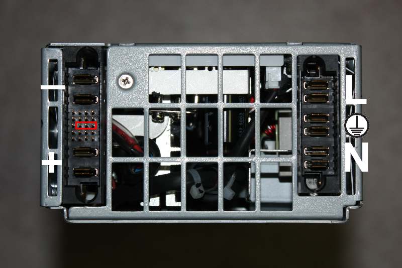
" Basically, it takes 2 things to max out the voltage increase. The max I could get is about 13.3V before it shuts down for over voltage. Below is a pin matrix of what to do. Basically, you short pins D1 and D2 together and put a 230 ohm resistor between C5 and B5. If you don't short D1 and D2 together, you will only get a voltage increase to 12.67V.
--1 2 3 4 5 6
D S S 0 0 0 0
C 0 0 0 0 R 0
B 0 0 0 0 R 0
A 0 0 0 0 0 0
S = Short
R = 230 ohm resistor
With a 30A load on the power supply, it holds a steady 13.3V"
Hope this helps. I guess it is a littl ebit different config.. but here is the enable:
someone posted these instructions on rcgroups so find the pins:
"Finding the voltage control pin is a process that also has the added benefit of revealing other important pins.
Attach a voltmeter to the output of the PS.
Record the base voltage reading. For example lets say +12.2v(+V).
Through a 750Ω - 1kΩ resistor, connect the +V output to each pin one at a time. This saves more time than having to find all ground, +3v and +5v pins.
Watch your meter as you connect to each pin to see if the +V output changes.
----------------------------------------------
If you get a +V change from only two pins than you've found both the
A: The +12v current share pin
and
B: The Voltage control pin. (+12 remote sense return)
The pin that changes the voltage the most will be the +12v current share pin.
The pin that changes the voltage the least will be the voltage control pin.
-----------------------------------------------
If you get a +V change from only a single pin then you've found either the
A: The +12v current share pin.
or
B: The Voltage control pin. (+12 remote sense return)
Repeat the process with a lower value resistor. Lets say from 500Ω to 749Ω.
If the +V change is the same as when connecting the first resistor than you've found the +12 current share pin.
If the +V change is different than when connecting the first resistor than you've found the Voltage control pin.
Always use one of the +3v or +5v pins when finalizing the main PS output voltage adjustment as this enhances voltage regulation.
-----------------------------------------------
In some instances you may also find the fan speed control pin. A minority of power supplies have this pin internally connected to ground.
Introducing a positive voltage to it will cause the fan to speed up.
The +12v current share pin can be used the fully regulate a PS as in post 470 or to vary fan speed in proportion to power
output as in post 461.
Hope this helps.."


")