JoeG:
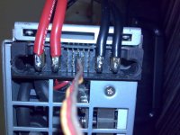
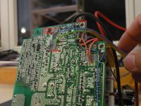
Can you show a detail of how you bolted the connectors onto the PSU's please. I luckily came apon quite a few of the actual counterpart (female??) connectors, but unfortunatly without the complete frame there are issues holding them in place... so no easy solution 8)
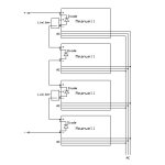
With only two PSU's I have been fine with only one diode in the output lead, with more than two supplies is it really nescessary to have them between each PSU??
...and whilst I am thinking on it I may as well pass on my thoughts on controlling the voltage.
In my case I only needed to control the voltage on one supply, which was nice and easy, so used the -ve terminal connected to the battery negative etc. as my arduino gnd, and the 12v off the same supply as +ve, with the PWM signal giving a nice clean rail to rail level through the unity gain buffer of 0-12v....
BUT for more than one supply there are two options that seem obvious to me:
1) Opto isolated PWM to the rest of the PWM->Voltage circuitry + an LM805 for each supply - Could be cleaner in terms of modularity.
2) Use ANOTHER I2C isolator and an I2C DAC with MAX232 to give -ve supply for that little extra top end voltage 8)
Much hubris, so would be interested to see what solution you come up with 8)
Note: Its a bad idea to use the same connector for low voltage signals and High voltage, but good to know an I2C isolator can protect from 100V short 8) I am sure you can guess what I did...
Can you show a detail of how you bolted the connectors onto the PSU's please. I luckily came apon quite a few of the actual counterpart (female??) connectors, but unfortunatly without the complete frame there are issues holding them in place... so no easy solution 8)
With only two PSU's I have been fine with only one diode in the output lead, with more than two supplies is it really nescessary to have them between each PSU??
...and whilst I am thinking on it I may as well pass on my thoughts on controlling the voltage.
In my case I only needed to control the voltage on one supply, which was nice and easy, so used the -ve terminal connected to the battery negative etc. as my arduino gnd, and the 12v off the same supply as +ve, with the PWM signal giving a nice clean rail to rail level through the unity gain buffer of 0-12v....
BUT for more than one supply there are two options that seem obvious to me:
1) Opto isolated PWM to the rest of the PWM->Voltage circuitry + an LM805 for each supply - Could be cleaner in terms of modularity.
2) Use ANOTHER I2C isolator and an I2C DAC with MAX232 to give -ve supply for that little extra top end voltage 8)
Much hubris, so would be interested to see what solution you come up with 8)
Note: Its a bad idea to use the same connector for low voltage signals and High voltage, but good to know an I2C isolator can protect from 100V short 8) I am sure you can guess what I did...
") There do I need to solder input and where is output + and -. Also, do I need to solder pins? 51.4V is OK for me.
There do I need to solder input and where is output + and -. Also, do I need to solder pins? 51.4V is OK for me.