ElectroSurf3r
10 W
Here is the Super V and Clown video thread:
http://endless-sphere.com/forums/viewtopic.php?f=6&t=39986
http://endless-sphere.com/forums/viewtopic.php?f=6&t=39986
")
REdiculous said:Large smoke bombs would probably work for visuals. Or a gang of smaller smoke bombs. Might find 'em on sale since the 4th just came and went.
A special-fx smoke machine would be a bit more expensive up front, and it might lack the volume you're after, but refills are cheap. *shrug*
A handful of leaves makes a fair amount of smoke ... low-tech and free.
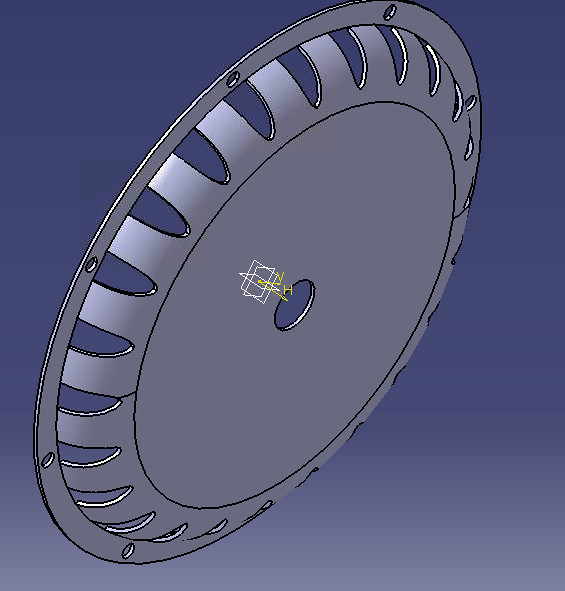
gensem said:What do think about the placement? I ll probably use a 6mm drill and a wide angle.

I ll try to do the blades tomorrow. (hope they are not hard to do)

gensem said:Hancock might be happy but im not so happy on the shape that the blades should have.
Im trying to imagine how could I shape the blades in a way to push the air to the perimeter... The way your blades are John the air will probably flow to everywhere inside the hub eventually reaching the outtake holes.
A simulator would be so helpfull...
gensem said:I hope I did not went too far...
I have 2mm aluminium sheet at hand and a clearance of about 15mm, will see what I can do!
hillzofvalp said:I did holes like that to my original 9C... Now that I have CNC access I doubt I will ever do that again to a motor. I will upload revised cromotor cover design here. I'm interested in have the design fully critiqued and improved in this thread before I yank apart my motor again
John in CR said:*snip*
Regarding in at the top and out at the bottom is not at all what happens with a ventilated hubbie. They would make a chuffing sound, and the air would have to fight against centrifugal force. There have even been some who accidentally angled the holes in the wrong direction, resulting in a scooping type effect at the top where the holes are moving fastest relative to the outside environment, and the result was a hot motor. This happened because it turbulence at what should be the exhaust holes and flow was stifled.
*snip*
John
John in CR said:TehStork,
At the lowest point in the rotation, the holes are moving at a speed of zero relative to the outside world.
John