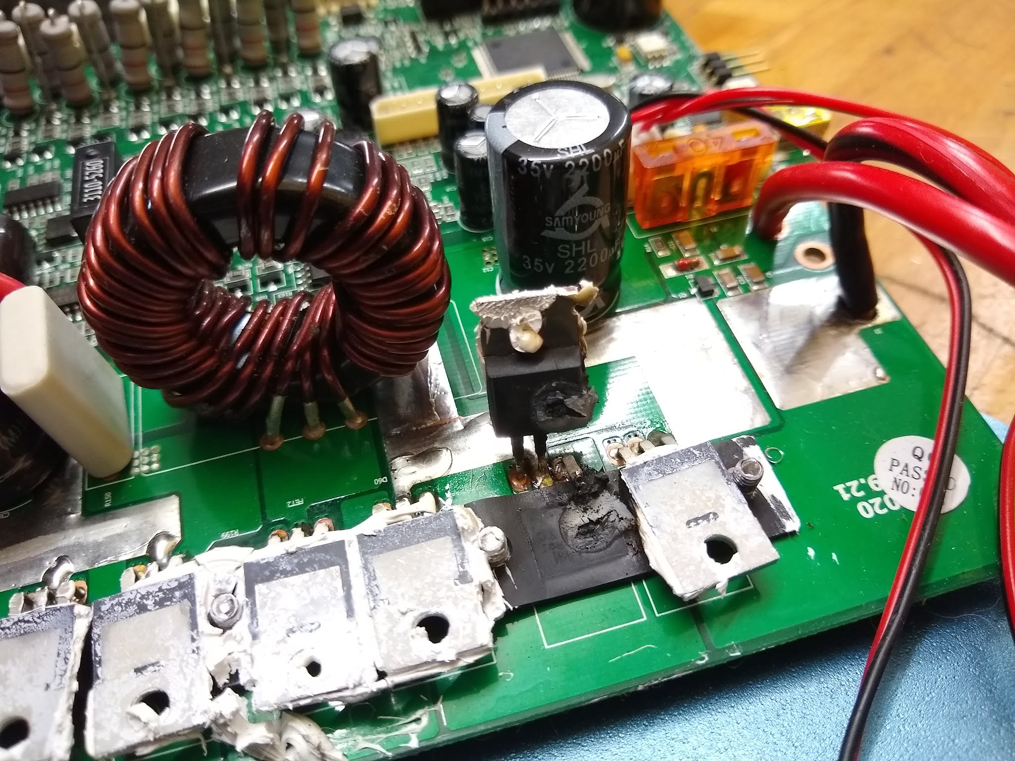
if you stand up the transistors, you can see there are some that are schttky diodes, and some are mosfets. the 4110 are n-channel mosfets and the 4905 are p-channel mosfets.
test the 4110 with your diode tester by putting the red probe on the drain leg and the black on the source leg. your diode tester should read open circuit. then reverse the probes with black on the drain and red on the source and it will tell you the forward bias of the body diode.
for the p-channel mosfets, 4905, you do the opposite. put the red probe on the source leg, and the black probe on the drain and you should see open circuit. then put the red probe on the drain and the black on the source and you should see the forward bias of the body diode.
the mosfet legs are gate, drain, source from left to right.
both of those schottky diode are called common cathode because the outside legs are the anode side and the center leg is the cathode. you can test them with the diode tester also but i doubt if they failed. more likely that the 4905 has failed, but check them all first.
if you look in the corner where the input voltage come onto the pcb you will see the 7805 three terminal regulator. go google the data sheet for LM7805 so you understand what it is doing. middle leg is ground, left leg is voltage input, right leg is voltage out. it should read 5V with respect to the ground when the charger is powered up on those input wires. so plug in the power supply to test for the 5V output of the regulator.

")