Identifying Shengmilo MX02 controller

smitel

100 µW
Joined
Feb 25, 2021
Messages
9
Here I'm organising some information I've collected on my Shengmilo MX02S bike.

Controller: EB09X1 D18461
Display: LCD-M5

Controller-display pinout:
1: Black - Ground
2: Cyan - UART Controller -> Display
3: Blue - UART Display -> Controller
4: Yellow - Only battery voltage when display is on
5: Red - Always battery voltage.

The baudrate of the UART is 9600.

P-settings out of the box:
P1: 3
P2: 0
P3: 48
P4: 10
P5: 1
P6: 26
P7: 1
P8: 100
P9: 0
P10: 2
P11: 1
P12: 3
P13: 12
P14: 13
P15: 39
P16: 10mile
P17: 1
P18: 120
P19: 0
P20: 0
 
I'm trying to find more information, OEM, datasheet, etc.
I doubt anything is available, and if it were, it would be in Chinese.
It's looks like a typical genaric Chinese square wave "torque imitation" controller(would have to see the display to know for sure) and most everything that can be known about it is in the pics.
The rating on the caps is 63 Volts, so that's about the limit of Voltage that can be applied (you would hit the motor limit first if the motor is a geared model, w/ a DD, maybe).
Max Amps are 18A, so max power is 860 Watts, not the 1000W listed on the label. Most likely it has two shunts (you don't show us that in the pics), but either way, single or dual it can be shunt modd'ed to 20 Amps max.
The 26" is recommended whl size I guess, the controller has nothing to do with the whl. size :roll:
It's big size suggests to me that it is a 9-FET, maybe even a 12-FET. From the pic, it looks like 1 FET per heat sink, so count the screws on the side. The low power/big size ratio means it will not likely get very hot, and since it looks like it's in some sort of box, that is likely the reason they are using it.
The LVC (Low Voltage Cut-off) listed is strangely low at 37 Volts. 40 to 42 Volts would be the normal value for 48 V controllers. I would look at the battery and see if it has a LVC, or at least what the recommended value is.
As for features, the display tells you that. Most likely the normal stuff for a genaric square wave, 3-speed limiter, PAS, cruise, ebrake cut-offs, the stupid 6 Kph speed limiter and maybe the even dumber 6 Kph "walk button".
A controller like that can be bought for $20 plus shipping all day, so if you have something specific you want to do, you need to buy something w/ options like a KT sine wave or if you are ok w/ spending some money, or a Baserun ner or Phaserunner with a Cycle Analyst.
Aside from changing the Voltage or Current slightly, that controller is not worth messing with.
 
Thanks for your extensive reply!

The controller is an LCD-M5. Same as on https://www.e-bikes.com/pages/nakto-ebikes-lcd-control-panel-instruction
There's some information on it, but most of it is very chinglish so I made my own list: https://docs.google.com/spreadsheets/d/1nhjLkB0kfXAkZBzQUNJlLB0Md8jKbuh_eqwtsADbpJQ/edit?usp=sharing

With regards to the LVC. There's no data on the outside of the battery. On the inside I can't find a PCB between the cells and the connector, so probably there's a PCB for this under the heatshrink?

I did find that one of the screws has damaged the tape and crushed the wires going to the power-level PCB.

The LCD has a current indication, but it never goes over 8A.
The controller has a P14 setting for current-limit, which I set to 22, but it still doesn't go over 8A.

I was hoping to find the OEM/type of the motor controller and maybe a wiring diagram.
Or are the the production runs of these parts usually very custom as to make most information not transferable?
For most connectors I can just follow the cable to the bike, but there's one unused orange/black connector from the controller.
 

Attachments

  • IMG_20210225_200436.jpg
    IMG_20210225_200436.jpg
    265.8 KB · Views: 4,685
  • IMG_20210214_133558.jpg
    IMG_20210214_133558.jpg
    348.5 KB · Views: 4,685
  • IMG_20210225_200357.jpg
    IMG_20210225_200357.jpg
    197.8 KB · Views: 4,687
What specifically are you trying to do? Knowing that may help us help you do it, without having to determine wiring, etc. ;) At least it will help us help you figure out if it is even possible without changing parts out.


smitel said:
With regards to the LVC. There's no data on the outside of the battery. On the inside I can't find a PCB between the cells and the connector, so probably there's a PCB for this under the heatshrink?
Probably. Easy to find the LVC by using a voltmeter on the battery positive and negative to the controller, and riding until it shuts off the entire display/etc. Whatever the last voltage is when that happens, is the battery LVC. ;) (unless there are problematic cells/groups, that run low well before others, which can sometimes be temporarily fixed by rebalancing it, which is usually easiest to do by leaving it on the charger for overnight to several days to several weeks depending on the severity of the problem).


But most likely the controller has an LVC that will shut it off (just stopping the motor) well before that happens, at the 37v listed on it's label.


The LCD has a current indication, but it never goes over 8A.
The controller has a P14 setting for current-limit, which I set to 22, but it still doesn't go over 8A.
The controller is probably hardwired for it's current limit, and doesn't have a programmable setting, to protect it's hardware. It may use hardware that simply can't handle more than that, or it may be hardwired (in hardware or firmware) for legal reasons for the market it is intended for. It's also possible the battery that comes with the bike is unable to handle more, and so the ocntroller is hardwired to not allow it. It's even possible that it is actually going higher than 8A but the software doesn't know how to display more.

The controller's label says "18A" current limit, which implies that the display itself is not capable of displaying hte full current, but again, could be the settings in the controller have been hardcoded at the factory to the 8A for whatever reason.


I was hoping to find the OEM/type of the motor controller and maybe a wiring diagram.
If you mean internal schematics, those are never available, unless drawn up by someone that owns one. Almost all wiring diagrams for external connections are very basic, if they exist at all, with may poor or outright wrong translations (even the original chinese markings can be wrong or very bad descriptions of the functions to start with).

The manufacturers of the controllers don't typically make them for sale to individuals, so they have no reason to make documentation available either. The companies that use the controllers don't typically sell to the end user either, and any documentation they do make, if any, only goes to the "dealers" (meaning, whoever buys a containerfull). Those "dealers" don't really want the purchasers of the bikes/etc that they sell to do any repairs--if they cant' fix them or modify them they have to buy a new one and they may get more business. For those places that buy and sell just controllers, if they even got any documentation from whoever they bought them from (which may or may not be the manufacturer), they may or may not pass that info on to the buyer. Some of them just post the first diagram they ever got, or found on the internet, even though the ones they're selling aren't that one and probably don't match the diagram.

So documentation of stuff like this is virtually nonexistent, except for threads like this where users have to figure stuff out. :(
 
Once again, thanks for your time!

amberwolf said:
What specifically are you trying to do? Knowing that may help us help you do it, without having to determine wiring, etc. ;) At least it will help us help you figure out if it is even possible without changing parts out.

The bike is sold as being 1000 watt, but I'm seeing just 8.0 on the display.
I'm curious to see if I can find if the controller and/or hub truely 'are' 1000 watt or if it's just upmarked.

Also just random curiousity.

Easy to find the LVC by using a voltmeter on the battery positive and negative to the controller, and riding until it shuts off the entire display/etc. Whatever the last voltage is when that happens, is the battery LVC. ;) (unless there are problematic cells/groups, that run low well before others, which can sometimes be temporarily fixed by rebalancing it, which is usually easiest to do by leaving it on the charger for overnight to several days to several weeks depending on the severity of the problem).

Ooooooooooh! When the battery LVC kicks in, the battery will disconnect the output until it's recharged?
I recently went out with half a battery to see how my bike behaves when out of juice.
In my case, the display starts blinking and shortly after this the entire bike shuts off and doesn't come back.

In contrast, my friends RadRhino goes into some sort of limp-home-mode. It doesn't turn off, but the power is greatly reduced.
Is this the controller reaching some low-voltage threshold and reducing the power to prevent the battery LVC from kicking in?

If so, there's an undervoltage parameter in my LCD that might have the same effect. It was set to 39v from the factory, but maybe that's too low.

smitel said:
The LCD has a current indication, but it never goes over 8A.
The controller has a P14 setting for current-limit, which I set to 22, but it still doesn't go over 8A.
The controller is probably hardwired for it's current limit, and doesn't have a programmable setting, to protect it's hardware. It may use hardware that simply can't handle more than that, or it may be hardwired (in hardware or firmware) for legal reasons for the market it is intended for. It's also possible the battery that comes with the bike is unable to handle more, and so the ocntroller is hardwired to not allow it. It's even possible that it is actually going higher than 8A but the software doesn't know how to display more.

The controller's label says "18A" current limit, which implies that the display itself is not capable of displaying hte full current, but again, could be the settings in the controller have been hardcoded at the factory to the 8A for whatever reason.

The display goes from '000.0' to '008.0' in '001.0' increments.

With regards to the current limit, in many specs I see talk of 'maximum current' vs 'nominal current'. Often the maximum' is roughly double of the nominal. This makes me think the nominal of mine is probably half the 18A.

I was hoping to find the OEM/type of the motor controller and maybe a wiring diagram.
If you mean internal schematics, those are never available, unless drawn up by someone that owns one. Almost all wiring diagrams for external connections are very basic, if they exist at all, with may poor or outright wrong translations (even the original chinese markings can be wrong or very bad descriptions of the functions to start with).

The manufacturers of the controllers don't typically make them for sale to individuals, so they have no reason to make documentation available either. The companies that use the controllers don't typically sell to the end user either, and any documentation they do make, if any, only goes to the "dealers" (meaning, whoever buys a containerfull). Those "dealers" don't really want the purchasers of the bikes/etc that they sell to do any repairs--if they cant' fix them or modify them they have to buy a new one and they may get more business. For those places that buy and sell just controllers, if they even got any documentation from whoever they bought them from (which may or may not be the manufacturer), they may or may not pass that info on to the buyer. Some of them just post the first diagram they ever got, or found on the internet, even though the ones they're selling aren't that one and probably don't match the diagram.

So documentation of stuff like this is virtually nonexistent, except for threads like this where users have to figure stuff out. :(

That's a shame. In other topics, like motherboards, USB sticks, etc. it's not uncommon for manufacturing tools and documentation to leak out.

For example: https://www.usbdev.ru/files/

These are the tools for the chips that are on USB flashdrives. These chips are not sold to individuals. The chips are sold to manufacturers who design a PCB, buy some NAND flash, buy the controller IC, buy the connectors, etc. and create the USB flashdrive.

After all the components are assembled, soldered, etc. the controller IC is still empty, so the sticks go to a guy with a computer with lots of USB ports and they fill all the ports with USB drives and run tools like this to program the firmware on all the drives and set the variables as designed for this particular product.

Or sometimes there's a debug header on the PCB for the initial programming because the drive doesn't even show up on USB without firmware.

Maybe in the ebike world not a lot of computer-work is done in the factory and the guys doing the assembly don't have access to more bits than we do with the P-parameters?
 
smitel said:
The bike is sold as being 1000 watt, but I'm seeing just 8.0 on the display.
I'm curious to see if I can find if the controller and/or hub truely 'are' 1000 watt or if it's just upmarked.

Also just random curiousity.
That's always a good reason. ;)

As for the true wattages...a "1000w" hubmotor (continuous ability) is likely to be a DD hubmotor. If your bike is this one
https://www.amazon.com/milo-MX02S-Electric-Bicycle-Mountain-Hydraulic/dp/B0893QMF6F
then it's a smaller geared hubmotor that from what I can see in that particular ad might really be capable of 350-500w continous, and *maybe* 1000w short peaks. The 1000w geared hubmotors I'm familiar with are ones like the MAC, BMC, GMAC, and sometimes the Ezee is listed as such. I have a "1000w" by Fusin (no longer around) that is probably less capable than the Ezee in reality, based on motor internals, but is almost the same size externally.

For short peaks, a geared hubmotor with sufficient thermal mass might handle two or more times what it can handle continously, but without sufficient cooling or motor mass / etc., if you keep putting those peaks into it or push it continuously at that, it'll overheat because it cant' get rid of the heat fast enough. More copper/stator/magnet mass means more continous power with less heat created. (non hubmotors can spin much faster and thus be much smaller for the same power...if they are cooled well enough). Geared hubmotors can't get rid of all that heat very well because there are three layers to them, with two big airgaps inside blocking heat transfer.

DD hubmotors can do bigger peaks relative ot the continous power, and can also do longer peaks and often some amount higher than continuous rating if they are kept above a certain percentage of their no-load speed all the time, and/ore have sufficient cooling, partly because they have more thermal mass, partly because they have more stator/copper/magnet mass, partly because they only have one airgap for heat to cross.


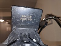
Controllers...generally I wouldn't be putting a 1000w controller inside a box with no airflow, and also generally that size controller will be 12-15FETs, where a 500w or less controller mgith only be 6 or 9. Your pics seem to show a controller about the size of the palm of my hand, which is likely a 6FET.

FWIW, I found this kit:
https://endless-sphere.com/forums/viewtopic.php?f=2&t=103162
at goodwill a while back, and while I don't know what the bike it came from was advertised as, the stuff I got with it that appears to all be from that bike is about a 500w max setup.


Oh, and a quick look on this model name finds this page
https://electricbikereview.com/forums/threads/sheng-milo-1000w-fat-ebike.35460/
which I only skimmed the first page and a half of, which doesn't sound good. :(


When the battery LVC kicks in, the battery will disconnect the output until it's recharged?
Depends on the BMS. Many only shut off until the load goes away, then come back on...this allows the user to beat the crap out of the battery until it is really really dead. ;) Maybe more fun for the user, not so great for the battery....


I recently went out with half a battery to see how my bike behaves when out of juice.
In my case, the display starts blinking and shortly after this the entire bike shuts off and doesn't come back.
The blinking display is probably the controller LVC. If the whole display shuts off, that's probably the battery LVC.


In contrast, my friends RadRhino goes into some sort of limp-home-mode. It doesn't turn off, but the power is greatly reduced.
Is this the controller reaching some low-voltage threshold and reducing the power to prevent the battery LVC from kicking in?
Very likely. If the RadRhino is from Radpower bikes, then it's probably this. Someone else I helped out locally here had a Rad bike with a similar protection, which was not user-alterable in that system. (partly this is so the company doesnt' have to deal with hammered battery warranty claims and other such troulbeshooting headaches).


If so, there's an undervoltage parameter in my LCD that might have the same effect. It was set to 39v from the factory, but maybe that's too low.
39v is reasonable for a 13s 48v pack, as that is still 3v / cell, which you might see under load when the battery is low. But if you don't mind a bit less range in trade for a longer-living battery, upping that as much as you can may help that (it will just shut your ride off sooner).


smitel said:
The display goes from '000.0' to '008.0' in '001.0' increments.
Do you mean the setting menu, or do you mean the active live display while riding? If the former, there's no guarantee that the number actually means amps directly, but may represent divisions of the maximum amps the controller is capable of. However, if it really is a 6FET (or even 9) controller, 8A is a reasonable maximum limit for it.


With regards to the current limit, in many specs I see talk of 'maximum current' vs 'nominal current'. Often the maximum' is roughly double of the nominal. This makes me think the nominal of mine is probably half the 18A.
That's possible. Ratings on ebike stuff is unfortunately largely a matter of marketing. What things are actually capable of continously working at without affecting lifespan or risk of failure (and sometimes what they can even do at all) doesn't always (often?) have much to do with what the sellers advertise them as. Even manufacturers are not unlikely to label things as far more capable than they really are. It's all about making money, and when this stuff goes outside China for sale, those sellers and manufacturers are unlikely to have to deal with the problems this creates, so they have no incentive to do the right thing instead.

Many sellers outside China don't care much either, even if they have a clue (which most don't) about what the stuff they sell can *actually* do vs what it says it can do. Some even make the problem worse, by exaggerating the already-exaggerated claims. :roll:

There are a *few* knowledgable and simultaneously reputable places...but not many. The only good one I have had any direct experience with is Grin Tech, http://ebikes.ca , though Radpower hasn't caused any grief via misinformation to the couple of locals I've helped out.


That's a shame. In other topics, like motherboards, USB sticks, etc. it's not uncommon for manufacturing tools and documentation to leak out.
Yeah, although it doesn't always make things better, like in this case. I think that this leakage of documentation may have resulted in the plethora of fake-capacity USB sticks out there (and similar stuff might have done the various fake-capacity memory cards).

But we cant' fault the documenters for the assholes that take advantage of others. ;)


User-documentation of ebike/etc stuff is one reason this forum exists, though, so feel free to post anything you do find about anything you run across like that for EV stuff. :)


Maybe in the ebike world not a lot of computer-work is done in the factory and the guys doing the assembly don't have access to more bits than we do with the P-parameters?
I doubt the assemblers do more than physically slap the stuff together as fast as they can possibly manage without killing themselves, and probably for as long as they can do it without collapsing from hunger and fatigue, for "wages" that many (hopefully but not realistically all) of us would consider criminal slave labor.

It is likely that the programming is generally done during the original board-manufacturing stage just after the point they have the MCU and all the other SMD bits on there (probably a single process), even before they stick on the FETs and other thru hole parts, as almost no controller I've ever seen ever has (or had ever had) anything soldered to the programming port pads on the board. That implies a process that just presses a programming "cable" or fixture to the board long and hard enough to verify and setup the MCU with the specific firmware and settings for that run of controllers. Even the people doing that work probably know nothing about the stuff going in there, and most likely only know enough about the process to ensure it is occuring. (assuming it is not completely automated, which at this stage of manufacturing is easily possible).

I seriously doubt any of these things get programmed or setup later in the process, after being assembled into housings with wires, and especially not after they're on OEM bikes. It would just take too much time and training and labor.
 
amberwolf said:
User-documentation of ebike/etc stuff is one reason this forum exists, though, so feel free to post anything you do find about anything you run across like that for EV stuff. :)

Makes sense.

I'm not sure how to organize the data in a constructive manner though.

For instance, on https://electricbikereview.com/forums/threads/m5-lcd-replacement.35845/ they're talking about the LCD-M5 and controller using a 'standard' protocol to communicate called 'Kingmeter 618U / J-LCD'.

So I guess should I try to hook my DSO Quad into the UART between my LCD and controller, learn how the UART mode of my scope works and see if this matches?

It does seem to mean there's a group of controllers/LCDs using the same protocol to communicate?
Or like a bunch of protocols. 5S, J-LCD, etc.

I guess it boils down to, what am I trying to achieve. Myeah. That's a good question. I just kinda like to figure stuff out.
It's probably best to set myself some clear goals, like trying to organize the connectors of the controller and maybe figure out the controller/LCD protocol and maybe figure out the OEM of the controller.
Otherwise I'll just end up wanting to map out the entire ecosystem. :)
 
I just kinda like to figure stuff out.
Your unrequited need to dissect, analyse and modify (a common malaise around here) leads me to believe that you would be a good candidate to start your first (of many) scratch, ebike builds.
My best advice to you is to put your store-bought ebike back together, ride it while construction of exactly what you want and then sell it.
Like most anything, any mods will likely decrease it's value.
 
First, given your statements so far, I'd actually go with Motomech's advice, of leaving the existing bike alone, and then simply building a whole new bike that does things the way you want them to, and then perhaps selling the other one to pay back a small part of what development cost. ;)

That said:

smitel said:
I'm not sure how to organize the data in a constructive manner though.
That's likely something that will self-organize as you do it. :) (or rather, it will become apparent how to organize it as you attempt to do so, kind of like programming). However, even without organization, the information itself is still useful to those that find it. :)


For instance, on https://electricbikereview.com/forums/threads/m5-lcd-replacement.35845/ they're talking about the LCD-M5 and controller using a 'standard' protocol to communicate called 'Kingmeter 618U / J-LCD'.

So I guess should I try to hook my DSO Quad into the UART between my LCD and controller, learn how the UART mode of my scope works and see if this matches?

It does seem to mean there's a group of controllers/LCDs using the same protocol to communicate?
Or like a bunch of protocols. 5S, J-LCD, etc.
There are a number of protocol threads here on ES (mostly with that word in the first post or title, making htem relatively easy to find even with PHPBB's crappy search function), if they are useful to you. There are also some open-source firmware threads for various controllers and displays, which probably have detailed info in their github/etc repositories that will likely save you some effort, if your display is among them. Casainho, Stancecoke, Andrea(I forget the #s), and others have been doing this for a while now. :)

I do know that there are at least several (known) different communication protocols, and even within the same protocol different models and versions of the same displays and controllers have different menus and acceptable settings and/or ranges of values for those settings, very little of which is documented anywhere.


I guess it boils down to, what am I trying to achieve. Myeah. That's a good question. I just kinda like to figure stuff out.
This is a good forum to be at, then. ;)


It's probably best to set myself some clear goals, like trying to organize the connectors of the controller and maybe figure out the controller/LCD protocol and maybe figure out the OEM of the controller.
Otherwise I'll just end up wanting to map out the entire ecosystem. :)
That's a common problem. I've found it's best to take very small nibbles of a project, wherever possible.

I would like a system that simply does what I want it to...but I haven't ever found one, so I've been slowly defining what that is, and building the bits and pieces to do it, often using other bits and pieces that do parts of what I want, and modifying as needed to get them closer. I'm now in the process of learning how to use Arduino stuff so I can use Nanos and the like to do little bits of stuff that other things don't do (or don't do the way I need to, so the Nano will then "trick" them into doing it my way).
 
Unfortunatly, I don't have the space to do proper work on a bike. But I'll keep your advice in mind for the future.

For now, some more findings:

- The P14 current limit has no effect.
- The P15 undervoltage setting has no effect. No blinking LCD. No limp-home.
- There's 3 screws on the side to attach the heatsink, but 9 mosfets inside

In the meantime I have disassembled the controller a bit further.

IMG_20210307_104810.jpgIMG_20210307_104837.jpgIMG_20210307_104908.jpgIMG_20210307_105230.jpg
IMG_20210307_103603 (1).jpg

Some preliminary googling turned up https://electricbike.com/forum/forum/main-forum/diy-discussion/96131-help-please-converting-a-pedal-assist-only-to-thumb-throttle-for-my-fortis-20 which seems very close to my controller.
The Fortis 20" Foldable Bike looks suspiciously like a Shengmilo MX20, which is explains the similar controller.

Googling on most of the pin silkscreen (P1, AX1, TB, TA, SP, SP5V, +5V, CR, SC, SB, SA, GND, +5VP, RX, TX, BKL, VB2+, KK, AX2, VB-, VB+) doesn't result much useful, but I've added them for when other people are googling. :D

My type: EB09X1 D18461.

- The SDA/5V/GND header on the frontside of the PCB attracts my attention. The SDA goes to a via, and then pops up on the other side to go to the F-XC836 controller. But it can't be I2C, because this would also need SCL. Maybe I should attach my scope and see what I see.

- Maybe somebody can recognize the OEM or other terms to get more information on this?

amberwolf said:
I'm now in the process of learning how to use Arduino stuff so I can use Nanos and the like to do little bits of stuff that other things don't do (or don't do the way I need to, so the Nano will then "trick" them into doing it my way).

I have an idea for an Arduino in-line with the display/controller. Sometimes I ride on the road, sometimes on private land. Different rules apply. If I could have the Arduino switch between modes with a simple switch that would save a lot of hassle.

- Searching for "XC836" + bike controller gives interesting hits.

https://endless-sphere.com/forums/viewtopic.php?t=81176
Seems to be the same OEM/design, but smaller. Same pin-naming, same style of silkscreening pin labels, etc.
Type: 706AX3

https://electrotransport.ru/ussr/index.php?msg=1452395
Some russian being told not to spam his pictures in an on-going topic
Type: EB06A4

https://electrotransport.ru/ussr/index.php?msg=1521352
Russians reverse engineering an 'MC Kumi controller'.
Type: EB06A2

https://electrotransport.ru/ussr/index.php?msg=1808833
Schematic diagram of the stock controller of the Kugoo S2 motor-wheel (EB06A2-836R02).

I guess the Kugoo S2 scooter has an EB06A2 controller?
It's probably useful to try to piggyback on Russian research.
They're awesome at reverse engineering.

https://electrotransport.ru/ussr/index.php?topic=54511.msg1568206#msg1568206
Shows the EB06A2P board inside a case with manufacturer name: Jinhua Huihao Electronic Technology Co. Ltd

It seems like the Kugoo S2 controller can be in two variants. Either with XC836 like this, or with STM32.

https://www.enbicielectrica.com/t4197-el-post-de-las-modificaciones-a-controladores#72825
Talks about EB712XC.

20140502_155631_zps4f2cc252.jpg
On their board is a 5-pin header near the 5V/SDA/GND header.
I read on some boards complaints that the board used to be programmable but newer PCBs no longer have this feature.

Maybe this is because these day the UART is used for communicating with the LCD, so maybe the programming goes through the same port, so they don't need a seperate header on the board anymore?

https://imgur.com/gallery/8uGg8
Has a EB712XC PCB inside a Grinfineon branded case.

Grin Technologies is a small Canadian shop. I don't think they'd be the supplier of Shengmilo, Kugoo, etc. controllers.
Maybe Grin Technologies has the same OEM as Kugo/Shengmilo/etc. ?

It seems like many people are talking about 'Infineon' controller, but I can't imagine the german semiconductor manufacturer Infineon to be producing these controllers. It probably refers to the MCU on the board, and it seems like it's all from the same factory.

"The Grinfineon SineWave controller is based around the popular Xie Chang device with the XCKJ3232C control chip".

Maybe Xiechang is the OEM?
 
I've tapped the UARTs between display and controller.

On the light blue pin, it repeats: 020E01004000000000000000004D until I hold the poweroff button, then it goes to 020E0100400000000BB8000000FE
Ont he blue pin, it repeats: 011401020180010104050100641601B800004C10

Hm, worth checking out https://github.com/jenkie/Arduino-Pedelec-Controller/tree/master/Arduino_Pedelec_Controller to see if it matches with any. :D
 
For what it's worth, I've been reverse engineering my MX02S and collected the data.

https://erik-smit.github.io/2022/04/23/shengmilo-mx02s-infos.html

Contains connectors, pinout, some UART protocol decoding, etc.
Could be useful for some people troubleshooting
 
Back
Top