Im going RC LiPo - General advice / BMS / Charger (also Build Thread now)

i just ordered the BMS16-T

It's customizable and can balance up to 1.2A.

i'll report when it gets here.

has anyone had experience with https://www.stefansliposhop.de/ ?

RC people seem to like the packs, and there are ready made 14S and 7S with 10AH... seems interesting. also HK cant ship from uk because of the pandemic :/
 
DogDipstick said:
I run at 6.6C and drop about 1v / 1000w output for the pack of LG (Chevy Volt chopped up) cells from GreenTec Auto.

do you mind me asking where you put those relatively huge cells?
 
Wummi said:
DogDipstick said:
I run at 6.6C and drop about 1v / 1000w output for the pack of LG (Chevy Volt chopped up) cells from GreenTec Auto.

do you mind me asking where you put those relatively huge cells?

Well, the one place they fit and help keep the front down on hard takeoffs from standstill. Lol. At the loss of about 2" of travel, might I add. Hey 1200Wh is what it is. Wh get ya far on ebikes and I like far. Lol. People look at my bike and can obviously tell 1: that it is an ebike, and 2: It got some good range. Lol. 20 mi on 50A and alot more on lesser currents.
 

Attachments

  • Globe.jpg
    Globe.jpg
    193.5 KB · Views: 417
Update Time!

I got two 7S 10AH packs

Chargery 25A Charger
and BMS16T

First the bad: The charger pooped itself after just 5 min of 10A Charging, my Home fuse popped.
I was able to diagnose and repair it with help of Jason from chargery over two weeks sending mails back and forth. Great service! It turned out the PFC Circuit popped it's FETs because of a faulty resistor. Still, i'd rather have it work from the factory, but oh well.
ncH.jpg


The good:
4II.jpg

This BMS is worth it's money except for one point: Balance current is 1.2A per cell. but it is temperature controlled and has a heatsink that is too small and inside an aluminium case. Balancing will take for ever on large capacities due to this.

i put a CPU heatsink with fan on it:
jQ8.jpg


And Balancing was done in a breeze! (Jason mentioned a newer version coming out with a dedicated fan control port)

Otherwise it's nice - 2 Temp sensors, external shunt and relay, loads of configurability and balancing down to 3.6V (i think)
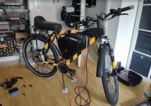
i fitted it in an additive triangle bag. (no more bulky LiFe Packs, hooray!)

LW9.jpg


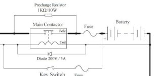
this now contains the batteries, BMS, fuse, shunt and contactor :bigthumb:

Yesterday i was able to do a quick test drive - sadly the weather has been shit since then.

i pulled ~75A without notable sag and it goes quite well.

Question:

I have a LYEN MK2 18 Fet - how many amps can i push trough before the magic smoke escapes?
Anyone got expieriences ? - Lyen just told me back in the day:
he recommended maximum output for the 12 FET 4110 controller is around 3500 watts and the 18 FET controller is around 5250 watts. Power=V/I. So let say you are going to run 22S lipo at 81.4v nominal voltage. You then divide 3500 watts by 81.4v and you get around 43A for the 12 FET, 5250/81.4=64.5A for the 18 FET. Or for 24S is 3500w/88.8v=39.4A for the 12FET and 5250/88.8v=59A for the 18 FET.

that would equate to ~100A. Good idea? :D
 
I don't have a direct answer for you, but some points to consider:

The FETs themselves have a current limit, usually in the leads to the FETs from the board, and the interior leads to the die from those external leads. This equates to a phase current limit which is higher than the battery current, because of the way the controllers work...but these controllers cannot sense the actual current in the FETs, and just calculate it based on internal settings (battery/phase ratio) and the battery current limit (assuming no shunt mods, which disable the ability of the controller to know what the current actually is, and thus unable to protect itself).

You can look up these lead and die limits in the spec sheet for the FET used, and there is likely discussion in old modding threads (especiallly by Methods, Fechter, Liveforphysics, and others around a decade ago when these were the best you could typically get or hotrod) concerning these limits. Most of them will be about "infineon" controllers.

Then there is the ability of the FETs to dissipate the heat generated in them, thru the multiple layers of thermal barriers between the die and the air outside the case, and then the airflow over the case's ability to carry away the heat that does finally get out of the case.

Then there is the wire thickness, both phase and battery, vs the amount of airflow over the wires, vs the time you'll be using that much current.


Oh, and this discusses the fet heating issues
https://endless-sphere.com/forums/viewtopic.php?p=1565550#p1565550
 
Things seem to be running well at ~75A, i'll leave it at that for the moment

i got a replacement BMS16T unit from jason - this is also working well and balancing good.

the "100A" DC Contactor supplied by Chargery has a ~15Ohm winding, at 12V this means 9W of waste heat, and it got really hot

i built a simple economizer:

and now were at about 4W - much better. I taked to jason from Chargery and he may implement a PWM economizer into the BMS Firmware, which would be great.
wQA.jpg

If none of this helps i might switch to a KiloVac Contactor.

I'm also thinking about wiring a precharge resistor directly across the main contactor (with a fuse) any objections from you guys?
pLa.jpg


worst case scenario: i twist the throttle without the main contactor engaged, poof goes the fuse and i have no more precharge resistor.

normal operation: plug in bat, wait a few seconds and switch main contactor on :pancake:
 
Wummi said:
worst case scenario: i twist the throttle without the main contactor engaged, poof goes the fuse and i have no more precharge resistor.

normal operation: plug in bat, wait a few seconds and switch main contactor on :pancake:

Wouldn't a diode on that line fix that issue?
 

Attachments

  • Ignition.JPG
    Ignition.JPG
    19 KB · Views: 305
DogDipstick said:
Wouldn't a diode on that line fix that issue?

the diode in your diagram is on the coil side, a flyback diode? https://en.wikipedia.org/wiki/Flyback_diode to protect whatever drives the coil. i don't need this, as the BMS that drives the coil already has this internally.

where did you get this shematic? it does exactly what i planned in my head, precharge resistor directly over main contactor :D :D
 
Wummi said:
a flyback diode?
where did you get this shematic? it does exactly what i planned in my head, precharge resistor directly over main contactor :D :D

Cool. Yeah I now see the difference..... It is the standard scheme that is in the Kelly Controller instruction .pdf. For ignition on the KEB model, ( and the others are similar I am sure).
 
Wummi said:
I'm also thinking about wiring a precharge resistor directly across the main contactor (with a fuse) any objections from you guys?
The only disadvantages to this are the one you state below, and that the controller "brain" and anything else powered by teh contactor will always be powered, and thus always draining your battery.

So if you for some reason don't use the system for a while, and forget to unplug the battery or otherwise disconnect it, you could drain it to the BMS cutoff point. Then, if the BMS has a parasitic drain on one or more cell groups to power the BMS, it may drain those cells beyond the ability to (safely) recover them.

Normally contactors are used *as* the battery disconnect, so ti doesn't have to be plugged and unplugged for any reason other than repairs

worst case scenario: i twist the throttle without the main contactor engaged, poof goes the fuse and i have no more precharge resistor.
You can also add an incandescent light, wired across the fuse (parallel to it), to let you know you've blown it. If it's lit, you know you've made a mistake. A more complicated alert circuit can be made, too, but this one is simple. Incandescent rather than LED so you don't blow up (literally explode) the LED and/or it's current-limiting resistor pulling too much current thru it.

The more complicated circuit can actually be used to disable the throttle until the contactor is engaged. I'm too wiped out ATM to see it clearly in my head, but it isn't too complicated, and can be done with just resistors and a transistor or few (and a small SPST relay if you want complete isolation). Basically it taps the driven end of the coil for trigger, and then interrupts power to the throttle until the trigger turns the circuit on.
 
amberwolf said:
The only disadvantages to this are the one you state below, and that the controller "brain" and anything else powered by teh contactor will always be powered, and thus always draining your battery.

So if you for some reason don't use the system for a while, and forget to unplug the battery or otherwise disconnect it, you could drain it to the BMS cutoff point. Then, if the BMS has a parasitic drain on one or more cell groups to power the BMS, it may drain those cells beyond the ability to (safely) recover them.

Normally contactors are used *as* the battery disconnect, so ti doesn't have to be plugged and unplugged for any reason other than repairs
in my case i remove the whole battery, including bms and contactor for charging / storage, so thats fine. i don't know how much current the LYEN draws idle / with iginition cable swiched off - i'm gonna check

You can also add an incandescent light, wired across the fuse (parallel to it), to let you know you've blown it. If it's lit, you know you've made a mistake. A more complicated alert circuit can be made, too, but this one is simple. Incandescent rather than LED so you don't blow up (literally explode) the LED and/or it's current-limiting resistor pulling too much current thru it.

The more complicated circuit can actually be used to disable the throttle until the contactor is engaged. I'm too wiped out ATM to see it clearly in my head, but it isn't too complicated, and can be done with just resistors and a transistor or few (and a small SPST relay if you want complete isolation). Basically it taps the driven end of the coil for trigger, and then interrupts power to the throttle until the trigger turns the circuit on.

i mean i'm gonna notice anyhow, because everything will be dark then :D

i thought about more complex systems, but all would require making more connections from my triangle bag battery to the rest of the bike - and i'd like to keep it easily removable. i think i'll check the idle draw of the controller and do it like i planned.


thanks for the input!
 

Attachments

  • Annotation 2020-06-29 225510.jpg
    Annotation 2020-06-29 225510.jpg
    197.7 KB · Views: 284
Back
Top