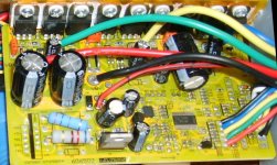
Infineon eb709xc Controller

Icewrench

10 kW
Joined
Sep 7, 2008
Messages
816
Location
Seattle Wa USA
So I blew up a controller that came with an ebikekit 9c and ordered a replacement.
What came in the mail is the next generation Infineon 9 fet controller,
a little different since there is no small red wire to switch it on and off with.
Fixed that by removing a solder bridge and adding a red/black wire to vk+ pad and out to my on off switch.

bridgeout.jpg

eb709xc.jpg

Next up on my list is to try to flash the programming but I don`t see this controller listed on the parameter desinger list. Hmmmm
 
i have same controlers and same problems ! impossible to active regen and cruise control :(
somebody have the solution ?
 
Please, if somebody knows something about those new boards (70X series), post it here...
It´s quite frustrating to have a new controller but can not program it :(
I have regen on it, but not the other fuctions
 
Hello all,

Well, you guessed it these are different from the old Infineon - thanks to whomever for posting this up as I just received one of these for testing from e-bikekit and just like you all I can't flash update it either... this is part of their new line of controllers with 3 spd and / or pedalec integration already but without the ability to flash them... well they are fine for normal 20mph "legal" ebike use but isn't flashing them half the fun?

So first I removed the solder bridge as mentioned above and then I gutted the R1A/B and R6 and all the caps - replaced them all with the intent of running 15-18S (75v max hot, 45v min LVC) so using a pair of 220 ohm resistors 2w slightly hit with a file to raise them to 230 +- 5 ohms, then series for a total of 455 ohms (perfect for this voltage range to keep things cool)... replaced the caps with 100v but doubt they needed it for 75v useage.

Now... I have an EB809XC and this newer? EB709XC on my workbench and I began tracing the apparent MCU flashing leads - what I found, near the actual 846 MCU rests a location for C14 which is missing... from the looks of it, (I will post pics later) it was removed on purpose as the solder thick (place it should be) is still in place... I know from experience that this MUST be present for the MCU to accept a flash but I have no idea the value..

Though I haven't finished tracing the rest of the circuit yet (and still may need to really screw with parameter designer to get it functional with the new firmware, if it's even possible) could one of you check your PCB just below the mCU for a SMT position for C14 - on the 709 it will be just above and left of D2 at the bottom edge of the PCB? I just wonder if mine "fell off" or was removed, anyone who could confirm this - I would appreciate it greatly..

And on I go with trying to flash this controller :)

-Mike

** EDIT: Can someone also please check the following on their EB709XC or EB712XC?

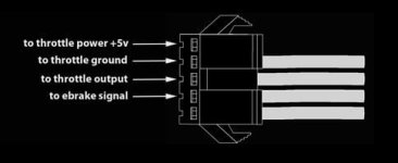
1.) Check the eBrake Cutout Plugs equipped in the harness for where they terminate - is it at the EBS- or is it between BK and GND?

2.) On the topside of the pCB - above and left of the MCU are 4 pads: AT, AB, BT, BB... anyone have more info on these?
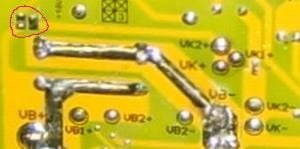
 
whats the date of manufacture on the board?
I was under the impression infineon chip is not used by xie cheng anymore? but since it has the infineon chip you should be able to get all the features working, lots of info on the forum on infineon chip going back a long time
 
I'm quite familiar with the infineon chip - the firmware is different somehow and is not even responding to parameter designer to error out... I believe the routine to update parameters in nvram is actually the "key" and is uploaded to eeprom memory, then executed via jTag / ISP interface... updated parameters are then loaded and "bootstrapping" or "flashing mode" is gone.

Still trying to dump the firmware from these to see how much sense I can make of Infineon ASM.

-Mike
 
just thought of something this afternoon, can you check the markings on the 846 chip, there are different versions, some dont have any flash memory! There was a post way way back that listed what the different markings meant. If its an older board xie cheng might have been using chips with no flash memory, maybe before they decided it was a good idea to publish programs that can be used with the controllers.........if you guys dont have the list of markings I can dig it out, i have on hard drive somewhere.
 
cancel that last post, seems they all have flash memory, but it can be protected from external access.
This doc XC864_um_v1.0.pdf not sure if its been posted before, buts its got about 480pages on the 846 chip ( 846/864 pretty similar i would guess)
 
Post a link please - some (most) had the read and write bits set but I may have a few custom sample units where the fuse bits weren't set and firmware is still readable from older versions, over write the newer version is what I'm thinking ;)

-Mike
 
http://www.infineon.com/cms/en/product/channel.html?channel=db3a304323b87bc20123dd3491af7017&tab=2
 
All I did for my 709 controller was to add a spot of solder to the shunt.


It now pulls 27 amps of battery current instead of 20.
Top speed is still the same @ 20 mph on 36 volts.
Acceleration is a bit better.
 
Just saw this thread and thought I'd point out to you fellas that the 709 is older than the 809, and is NOT reprogrammable. Flashed once at the factory, and can't be reprogrammed again. :cry:
You can lower the shunt resistance for more current, add a resistor to raise the LVC, and add resistance in series with the regulator so you can run higher voltage.
Bob
 
If anyone wants one of these controllers, I have a whole box full. $60us delivered. They have CA plug.
Shuts are clipped for 22amps but you can re solder them for 30ish amps.

Also, the CR pad, which you think would do cruise actually does reverse.
Unable to activate cruise.
Regen works.
 
So I take it no support for parameter designer or key win lab tools to fine tune programming?
Regards,
Mike
mwkeefer@gmail.com
 
Im not even going to try to program these. Enough controller headaches.

Can some one who has PAS on this controller tell me which pad is the PAS signal.

Cheers.
 
There's a pinout for that in one of the CRystalyte threads, I think.

EDIT: found some info here:
http://www.endless-sphere.com/forums/viewtopic.php?f=2&t=25881&start=0

You should be able to match that up with the PCB and wires.
 
Back
Top