Killed my BMS on my BH Neo Battery

Melbourne

100 W
Joined
Jan 18, 2013
Messages
123
Location
Melb,Aust
So i brought a Bafang crank kit and 36v bottle battery... unfortunately bottle battery sux, so I connect in parallel my 1 yrs old Neo battery to give a bit of power and it makes a Big difference in power.

So for 3 weeks i was very happy :) and start hammering the batteries with alot of throttle up hills. Yesterday... the neo battery will not charge with the oem charger and stuck at 37V, and also notice a slight smell of burn electronic (BMS fried??)...:(

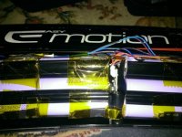
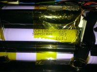
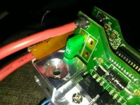
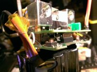
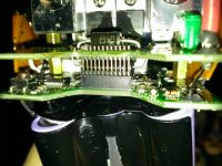
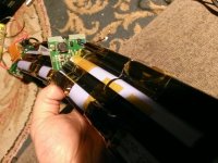
So open up the battery...BAD Idea. double-side tape everywhere.... DAMN. Looks like 5 packs of 8 battery..Total 40 samsung batteries.
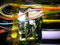
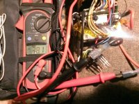
After 1 hour, took the bms and batteries out ....Look thru the electronic and did see anything burn but VERY distinct smell of electrical burn. Unscrew the battery red/black wire and bypass the BMS... connect to charger and charged up to 41V... connected to the bike and everything back to perfect, commuting to work.

so the plan is to charged to 40v, monitoring the battery carefully and use the battery until it dies... without BMS, i don't think i will have much luck with BH as their support/warranty sux. Sound like a Good Plan??? it ok?

Funny thing i ordered lifepo just last week for the crank kit.:/

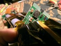
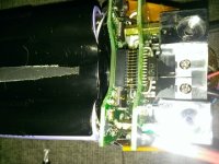
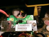
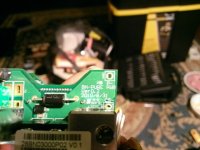
WP_20131113_007.jpg
WP_20131113_008.jpg
WP_20131113_009.jpg
WP_20131113_013.jpg
 
did you ever measure the cell voltages before you removed the BMS and charged without it? did you do anything to determine why the BMS is not allowing it to charge? can you take pictures or test any of the components of the BMS? do you wanna buy another replacement BMS if you cannot examine this one?
 
dnmun said:
did you ever measure the cell voltages before you removed the BMS and charged without it? did you do anything to determine why the BMS is not allowing it to charge? can you take pictures or test any of the components of the BMS? do you wanna buy another replacement BMS if you cannot examine this one?

Yes... 37v from the battery and from bms. Not sure how to determine Bms not allowing to charge.

I will take more pics tonite.

Yes, if possible... i can buy one.

Thnx Dnmun
 
the fuse may have burned and you now are bypassing the fuse as well as the BMS. it is pretty easy to test them but you need to measure the individual cell voltages to know what is going on with the battery.
 
dnmun said:
did you ever measure the cell voltages before you removed the BMS and charged without it? did you do anything to determine why the BMS is not allowing it to charge? can you take pictures or test any of the components of the BMS? do you wanna buy another replacement BMS if you cannot examine this one?

Been commuting with the battery, so discharged/charged a few times between 38V to 40V.

Measured the individual cells all seems to be same range 3.87V<->3.88V, well balanced, measured a total output 38.7V.

Reconnect the BMS, measured of 38.1v,

Connect to bike, press on button lcd turn on for few sec and lcd turn off.

Connect to charger..input charger-BMS voltage 41.7V, output BMS-batteries 38.7V.

Measure fuse resistance 0 ohm ... press mini(reset?)button..not changed

will post pictures soon.
 
BMS voltage
WP_20131115_030.jpg

fuse
WP_20131115_005.jpg

reset button?
WP_20131115_015.jpg
WP_20131115_013.jpg

another hidden pcb between battery pack
WP_20131115_028.jpg
WP_20131115_026.jpg

Random pics of main bms
WP_20131115_006.jpg
WP_20131115_022.jpg
WP_20131115_025.jpg
 
your BMS is really different because it has a swithc mode power suplly circuit so it can provide the circuit current to run the ICs from that top level pcb. the inductor is the thing with 470 printed on it.

you want to measure the gate source voltage on those two little 4310 knockoff mosfets. use the 20V DC scale on your voltmeter. the legs are gate, drain, source and you wanna see what the voltage between the gate and source is.

also you should double check that resetting circuit breaker you said you pushed down. check continuity across that breaker with your ohmeter while the board is disconnected from the power. ie when the red wire is removed from the BMS.
 
dnmun said:
your BMS is really different because it has a swithc mode power suplly circuit so it can provide the circuit current to run the ICs from that top level pcb. the inductor is the thing with 470 printed on it.

you want to measure the gate source voltage on those two little 4310 knockoff mosfets. use the 20V DC scale on your voltmeter. the legs are gate, drain, source and you wanna see what the voltage between the gate and source is.

also you should double check that resetting circuit breaker you said you pushed down. check continuity across that breaker with your ohmeter while the board is disconnected from the power. ie when the red wire is removed from the BMS.
hi dnmun

Power MOSFET IRFB4310
no voltage(~1.3mV) between the gate and source... connected/not connected to charge.

Don't know is relevant...but a day before the battery stop charging...i notice a strange charger behaviour...fan stop(stop charging) for a few min and start(start charging)a few mins and did this a few times at the end of charging cycle.
 
that is why it is not charging then. the mosfet is not turned on. there are 11 pins of the sense wire plug that are soldered to the pcb directly in front of the mosfets. the one on the far right in your picture is the B0 pin, i think.measure the cell voltages between those adjacent pins starting with B0-B1, B1-B2 and so on up to the last one, B9-B10.

you can put it on the charger while measuring if you want but it is not gonna charge if the mosfet is turned off.
 
dnmun said:
that is why it is not charging then. the mosfet is not turned on. there are 11 pins of the sense wire plug that are soldered to the pcb directly in front of the mosfets. the one on the far right in your picture is the B0 pin, i think.measure the cell voltages between those adjacent pins starting with B0-B1, B1-B2 and so on up to the last one, B9-B10.

you can put it on the charger while measuring if you want but it is not gonna charge if the mosfet is turned off.
hi dnmun
Are they the balancing wires?
Connected/not connected to charger
3.88
3.88
3.88
3.90
3.88
3.76
3.88
3.88
3.88
 
there should be one more but i expect it also i in that range but you should try to find it too.

so if there is not voltage on the gate there must be something that is killing the 12V rail that comes from the SMPS on the top board.

so now you need to expose that pcb enuff to take good pictures front and back.

but before doing that, while the entire battery is wired up normally with the red wire to the BMS and all connections intact, use your voltmeter to see if you can find the 12-15V on that top level where the SMPS is. it may be labeled saying Vcc or 12V or something like that or you may be able to find it by looking at the traces that go off to the ICs that control the mosfets.

that was why i asked about the pop up switch you said you had depressed to reset. if that is in the circuit from the SMPS you need to make sure it actually is a closed switch.
 
Back
Top