Lebowski's motor controller IC, schematic & setup, new v2.A1

Thanks Lebowski.

I figured out how to use another PIC to translate from 16bit data to human readable/terminal friendly text. The PIC will send e.g. 'f' to the controller chip and wait for 2 bytes to arrive from RS232. When the second byte has been received, the PIC will send 'z' to the controller chip and the controller chip stops sending data. This can be done at whatever frequency is suited for human reading (like 10Hz).

Now, what I don't understand is the format of the data received. It says in your manual:
Data is outputted as 2's complement with the high byte first.
This would mean that all negative numbers has a MSB of 1 and all positive numbers has a MSB of 0.
But why does e.g. the throttle 1 (sending 'f' to the controller chip) go from -32768 (0x8000) to 32767 (0x7FFF)?
 
Oops, my bad, the MSB is inverted before transmission, and strictly speaking not all are 2's complement.
Phases, currents, voltages are all 2's complement, but the throttle is not. It transmits the x1 and x2 from the manual, which
have a 0 to 1 range. So 0 would show up as 0x8000 (0x0000 after inverting the MSB back to normal) and 1 as 0x7FFF (0xFFFF
with the MSB corrected)

I'm not a professional manual writer, sorry :(

The way you read out the data is good though, send a character, nab the first 2 that get back and close down transmission by
sending a 'z'. It sends over 3500 words a second so if you loose track.... but Labview works excellent in getting a running graph.
 
Lebowski said:
I'm not a professional manual writer, sorry :(
Maybe you should reconsider what I have suggested earlier, making the manual "open source" so others can contribute to the manual when we ask questions and "discover" more detailed information. It would be a better reference for us users so we don't have to remember all from this long thread :wink:

Just to clarify, the 2's compliment is the way you deal with values that can be negative, right?
I think this is the way C compilers construct unsigned integers so your output is compatible with C-code.
 
I thought about it, but I'm afraid it'll get messy with 24 versions of the manual floating around. Plus it's all done in LibreOffice under Ubuntu, so not the standard ppt format.

The nice thing about assembly is that you can decide for yourself what the 16bit in a Word mean... In the controller IC at some points 16 bit is 0-65535, in other places -1 to 1 or even -8 to 8 .
 
Hi Lebowski
Rather than posting in Arlo1's thread... I thought here is more relevent.

Many Current sensors are ratiometric where the output signal is scaled to the supply voltage.
Could there be a way to apply this to the dSPIC30F2011 to improve accuracy of phase current measurement?

I am wondering ...
Is this really a problem ??
Or can it just be filtered out.
If the Current sensors have "rock solid" Supply voltages then that won't cause an error.
etc.

I'm thinking it can't be.

Had a look at this Thread's Page 1 for the Manuals of the your Lebowski Controller
"Albis motor controller IC"
??? Albis <<>> Aldiswill, Switzerland odd coincidence ???

And the ver 2.x has lost the choice of 2 or 3 Sensors

Ver 1.21 has : said:
"a) number of current sensors: 3 "
...
"Option a tells the controller how many current sensors are present, valid values are 2 or 3. "

Could the version 2.x algorithms use 2 current sensors?
Or a Version 3.x ?????

Does the pin out of the Brain need to be backward compatible to Vers 1 or Ver 2

Or Other 40 pin PIC Chips ??

So Brain Box - schematic_v2p30.pdf has Halls moved and Vbat added.

Looking at the Pin out of the dsPIC30F4011
DSPIC30F4011-pinout.jpg


The DSPIC30F4011 spec figure 20-1 10-BIT HIGH SPEED A/D FUNCTIONAL BLOCK DIAGRAM
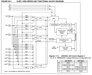
DSPIC30F4011 spec verG figure 20-1 10-BIT HIGH SPEED A-D FUNCTIONAL BLOCK DIAGRAM.png
[mg]http://endless-sphere.com/forums/download/file.php?mode=view&id=146360&sid=6f7b09f839adfeacd8de9bf4d3cba005[/img]

There are 9 bits in RB port pins RB0 - RB8 and matching 9 Analogue inputs AN0 - AN8

The ADC REF+ can be linked to AN0/RB0 or AVdd
The ADC REF- can be linked to AN1/RB1 or AVss
AS per ADCON2 <ADCG>

So Conversions can be scaled between a varying REF+ and AVss.


But the Vbat or a throttle 1/2 or spare Current would need to shifted around to allow access to REF+
To allow Current-Scale to be connected/shared.


The VINH-VINL is also definable as the connections to +IN an -IN of the S/H CHx x:O/1/2/3.

The VREF- is the bottom of the Window
The VREF+ is the Top of the Window

AD-RESULT = 1023 x (VinH-VinL)/(VrefPos - VrefNeg)
For an Unsigned conversion result

AD-RESULT = 511 x (VinH-VinL)/(VrefPos/2 - VrefNeg)
For an signed conversion result

So for VrefPos = Vref+ = AN0 = RB0 = SensorPositve_Divider
with for VinL = VinrefNeg = AVss = SensorNegative
and with VinH set to Pin Signal AN1-AN8 = SensorOut_Divider

So Unsigned AD-RESULT = 1023 * ( SensorOut-Divider - SensorNegative ) / ( SensorPositve_Divider - SensorNegative )
So signed AD-RESULT = 511 * ( SensorOut-Divider - SensorNegative ) / ( SensorPositve_Divider/2 - SensorNegative )


dsPic30F FRM Manual said:
Chap 17
17.16.1 Example: Sampling and Converting a Single Channel Multiple Times
Figure 17-11 and Table 17-2 illustrate a basic configuration of the A/D. ...
... The CH0SA bits and CH0NA bit are specified (AN0-VREF-) as the input to the
sample/hold channel.
..

Other Microchip ADC manuals helps make this clearer.

Sorry for the long post just hope my clarification could help others.

So Lebowski, would it be worth consider say a 2 Sensor based Algorithm again to free up AN0 to be used as Current_SensorSupply?

Or should the Sensor supply be run off a 12V-0V Railed OPAMP with the output set for 10V using a 5V(AVSS) as reference and able to supply 20mA + 20mA ?

Dank je
7Circle
 
It's as Futurama says, with the ADC reference at AVDD and AVSS both the ADC and any 5V current sensor (on the same supply) are radiomatic. So, any supply variations cancel out. It's a different story for 10V current sensors, but even then it doesn't have much of an impact because of the digital filtering inside the controller IC.

I decided to abandon the 2 sensor input option, just because it is bad electronics design. Noise on the output of the current sensors is made up of 2 components, one that is equal for both (like for instance coming from a bad power supply voltage) and each sensors individual noise.
If you use 'the sum of the currents is 0' to calculate the 3rd current, what you're doing is assigning all of the combined noise of the 2 sensors to the third current value. With a third sensor however each channel has only the second component, the noise from each channels current sensor (as the common noise component is completely eliminated by the algorithm).
So, faced with the choise of the 3rd channel having all of the noise of the other 2 channels, or the channels having each just a little bit of noise, it was easy to decide to elimitate the 2 sensor option...
 
I've read so many comments about Lebowski controller here at the forum and now I went to see what it is all about.
Then I read a few pages on a couple of threads and I am even more confused then I was before starting to read.

I see one bloke is doing a small form factor lebowski stacked on top of each other. Referred to as a "brain" whatever that might be.
Then I found this thread and tried to learn more by reading this, and after a few pages my head was about to explode and my brain was at it's melting point.

Could anyone do a quick explanations of the Lebowski controller and what is does and what makes the Lebowski stand out compered to other controllers like the Lyen, Adaptto, Kelly or a Sabvoton?

I mean it appears that there have been some major brain power going into making the Lebowski stand out from the rest of controllers. And with so many referrals here on the forum I figured they must be bringing something to the table. I just can't find
an easy to read and understand features list of what makes Lebowski a special controller.
 
The Lebowski controller is basically just the chip that calculates how to drive the motor. It drives the motor very quiet and efficient. The "brain" as we call it, is the Lebowski chip itself, it's the brain because it's here all the calculations and algorithms is going on.

Lebowski does not share the code inside the chip, it's his secret, but he does sell a programmed chip, ready to use for a reasonable price. He also keeps improving the code, sometimes he even take suggestions from forum members if the suggestion makes sense to him too.

Lebowski also came up with a low inductance output stage which he documented and tested in his own controller build. He even made a PCB design for everyone to use, so everyone could easily build their own controller based on his chip and platform.

Finally, Lebowski is very helpful when it comes to the controller chip (and other stuff too), if you buy a chip from him and have a problem, he won't hesitate to help troubleshooting.
 
Futterama said:
The Lebowski controller is basically just the chip that calculates how to drive the motor. It drives the motor very quiet and efficient. The "brain" as we call it, is the Lebowski chip itself, it's the brain because it's here all the calculations and algorithms is going on.

Lebowski does not share the code inside the chip, it's his secret, but he does sell a programmed chip, ready to use for a reasonable price. He also keeps improving the code, sometimes he even take suggestions from forum members if the suggestion makes sense to him too.

Lebowski also came up with a low inductance output stage which he documented and tested in his own controller build. He even made a PCB design for everyone to use, so everyone could easily build their own controller based on his chip and platform.

Finally, Lebowski is very helpful when it comes to the controller chip (and other stuff too), if you buy a chip from him and have a problem, he won't hesitate to help troubleshooting.


So let me see if I got this right. Do I need to build my own controller from scratch (not feasible) or can I add his chip to most any controller? If you add his chip into other controllers what can you achieve? How can I get the benefits of Lebowski into say a Lyen, Kelly, Sabvoton etc?

I like the idea of supporting clever minds of ES community and I much prefer to support and buy parts that ES members have developed and brought to life products or modified products for the greater goods of the e-bike community. And I would like to contribute by being their customers. But I think the Lebowski brain needs a bit tweak on the presentation part so non-electric-engineers really can easily see the benefits of using this chip. Especially if the chip is possible to use with most controllers.
 
The chip can't be used in existing controllers, you'll have to build your own controller.

The much talk about the Lebowski controller, is probably from those people that are building their own controllers from scratch, or from those dreaming of buying a ES member built controller. I'm one of those guys building my own controller, I can build the hardware, but the software for the chip would be just as big a project, but I can basically cut my DIY build in half since I can purchase the control chip from Lebowski and don't have to worry about control algorithms because all that is taken care of in the Lebowski chip.

I'm sure that eventually, someone like maybe ES member "zombiess" will have built a great controller using the Lebowski chip, and will either provide kits or finished controllers for others to build.
 
Are those chips firmware upgradeable? Can they be flashed with later firmware to add functionality?
 
Lebowski said:
7circle said:
Lebowski - nice work on the adabtable hall analyzer.

I noticed the manual V2.30 still discusses the older 2k2 divider style.
oops, my bad
Sweet so I can get ride of these 2.2k dividers? I notice the hall circuit is empty just 5v and gnd and halls to the plug. Im adding the hall support to my board so its available if I ever need it.
Just want to make sure of this.
 
Arlo,
Are you building up using Bas' board design?
I can't seem to get my BOM to print out properly.
Were you?
What version of kicad?
Thanks!
Chris
 
I can't get mine to work either. Not sure how to do it. But yes I'm making a brain board somewhat universal for all my projects.
post in the Kicad thread and we can all try to discuss it. This is something I would like to figure out. http://endless-sphere.com/forums/viewtopic.php?f=30&t=46191&hilit=+kicad
 
Arlo1 said:
Lebowski said:
7circle said:
Lebowski - nice work on the adabtable hall analyzer.

I noticed the manual V2.30 still discusses the older 2k2 divider style.
oops, my bad
Sweet so I can get ride of these 2.2k dividers? I notice the hall circuit is empty just 5v and gnd and halls to the plug. Im adding the hall support to my board so its available if I ever need it.
Just want to make sure of this.

I'm may have confused things as I usually call DC Current sensors "Hall Sensors" as they use hall effect to measure the current.
The Rotation sensors being Hall pickups in the motor stator field pickuping of the rotor Magnets.

"I noticed the manual V2.30 still discusses the older 2k2 divider style." << This refers to the phase voltage Neutral Divider in

This V2p30 schematic has P32 for Hall connection and R106,108 and 110 as 4K7 pull ups.
V2p30 pdf


Thew V2p30
the following schematic is for v2.30 and higher, note that the hall connections have moved:

The following schematic and manual are for the version with the HF tone (v2.00 and higher):
schematic_v2p00.pdf
Had them removed.

Make sure your schematic protects the Brain from spike, pos or negative.

What schematic are you using fro the dsPIC Pin OUT Arlo1???

[Edit - fixed up mixup]
[Edit - fixed the unmixed mixed up of links . thanks arlo1]
 
V2.3 and 7c you should edit you post because the sch for 2.3 does not show any components for the Hall motor position sensors.
I don't see a need for protection of a spike from a hall position sensor because it is fed 5v and gnd which in my design are form isolated supplies.
That way the dsPIC will never see more then 0-5v

I am building everything for the v2.3 chip to make life easy.
 
your building an ev .. not delicate lab experiment.

Static discharge from external connections can do nasty things to microcontrollers.

Just thinking of practical issue of protections from nuisance failures.

Or be vigilant in grounding procedures.
 
7circle said:
your building an ev .. not delicate lab experiment.

Static discharge from external connections can do nasty things to microcontrollers.

Just thinking of practical issue of protections from nuisance failures.

Or be vigilant in grounding procedures.
Chassis stays isolated.
5v supply for Brain and halls is isolated and the hall wires (which I'm not planning to use) will only be 5v with nothing grounding to the chassis it should not be a problem.
Static.... as in hooking up a wire?
 
"static" as why parts come.in anti-static bags.

The Hall 5pin wiring goes out of the enxlosure. It can get static charge. This can damage CMOS ic pins.
often these pins are protrcted with tvs diodes to the vcc and gnd rails.

It could be over kill. Just a warning
 
7circle said:
"static" as why parts come.in anti-static bags.

The Hall 5pin wiring goes out of the enxlosure. It can get static charge. This can damage CMOS ic pins.
often these pins are protrcted with tvs diodes to the vcc and gnd rails.

It could be over kill. Just a warning
I put a MOV on the 5v supply last time around and all the sudden I stopped burning up brain boards.
 
I just noticed the halls have 4.7k pull up resistors.

Do you really think you need 6x 47uf caps parallel to 6x 100nf caps? I think 6x 4.7uf parallel to 6x 100nf (.1uf) caps is ok isn't it?
I'm just about done re drawing the SCH. to work with all my powerstages.

EDIT:
I found a couple wires I needed to connect. I think I'm really close t don the SCH now.
Some things are options like the battery voltage and Phase voltage measurement pins.
 

Attachments

  • Brain2.3.pdf
    49.7 KB · Views: 79
Did you know you can import schematics into your schematic sheet like Copy and Paste.
- Lebowski has his KiCAD file for V2p30 here : 30F_pcb_v2p30.zip http://www.endless-sphere.com/forums/download/file.php?id=142967
You could then modify it to suit your design like delete off stuff you don't want.

The qty of caps depends on the pulse loads and your pcb layout placing them close to where they are needed.

The TPS1 connector pin out could be improved if you want 0V/Gnd next to throttle signals if it is a ribbon.
You might uses CAT5 cable with 4 twisted pair and shield around it. So 8 wires
and perhaps a Fault signal included for user display.
Perhaps Lebowski may be influenced to include a Fault input to the Brain ... Just to count the faults and if a better recovery is needed by changing operating Mode.

It might be worthwhile including R+C for all analogue inputs placed near the pins on the PCB.
( You have it for THrottles but K1 phase voltage go straight to connector with no pull downs so they will be floating if not used, and Current Sensors have just Cap.)

Be careful with Pin 11 on PCB for 5V as its the AVCC input. And 12 is AVss for analogue ground.
Some times a 0R resistor or inductor component will make it more obvious when placing track work.


Reverse could float ... keep the pull down..

P5 Halls could include a Temp Signal Circuit or Two Temp signals.
What signals would go to the Motor Stator?
But I do get carried away with options.. . that go nowhere ... unless you have a second brain chip.

CAN CAN dancing legs will need resistor across for termination of "transmission line".. perhaps protection diodes too.

Pin6 is for Battery monitoring ... will you include this.
Do you you need to?
Perhaps on K1 connector
It could be another 10 way ribbon with 4 gnd and a +5V for remote PCB.
I wonder if Lebowski would recommend Phase pick up at the motor end if a parallel bridge approach was linked at the motor stator side.
Say 9 Wires ran to the motor from 3 Bridge Blocks so cable inductance will help regulate phase currents.
Not what Arlin is going but he or someone else might later. (did a search and lots building power stages)
for convenient links said:
http://www.endless-sphere.com/forums/viewtopic.php?f=30&t=57877 Thread : build your very own Lebowski controller ! With KiCAD
http://endless-sphere.com/forums/viewtopic.php?f=30&t=55641 Lebowski's - low inductance output stage contruction
http://endless-sphere.com/forums/viewtopic.php?f=30&t=60369 Purple Jeeb & Bluefang - Lebowski controller build possible IPM output stage
http://endless-sphere.com/forums/viewtopic.php?f=30&t=63572 Beez65 - New Lebowski disciple!
http://endless-sphere.com/forums/viewtopic.php?f=30&t=57375 Futterama's power stage for Lebowski's controller IC with lots of Scope Shotts and QTFP surfacemount dsPIC on DIY pcbs
http://endless-sphere.com/forums/viewtopic.php?f=30&t=51342 ZombieSS's power stage for Lebowski's controller
http://www.endless-sphere.com/forums/viewtopic.php?f=30&t=30851&start=500#p518251 Arlo's - Not simple BLDC controller - When Big Lebow says "Just wait for my chip" Arlo's been hacking at his own dsPIC Code ... nice work.
http://endless-sphere.com/forums/viewtopic.php?f=30&t=35387&start=1900 Arlos Power Stage

Perhaps this is better discussed in a Arlo1 thread...
 
Yes I will tie what's not used to ground battery phase reverse etc. I will try to read this again at lunch and I will post a link to my leae controller thread.
 
Back
Top