Lightweight folder - build thread

Timely to just catch up with this thread. I am also in the UK and have just purchased an Xootr. At the moment it is pretty stock fitted with SRAM X4 derailleur gears. All I have done is to raise the bars and fit Big Apple 406 + 50 tires. This bike is just pure FUN. It is also VERY fast and rigid to ride. The Big Apples smooth out the bumps. I am almost reluctant to "e" it, but am planning on trying one of the new Tongxin Goldant 1.4kg motors. The standard 100mm spaced front dropouts take a motor without any modification (you don't need to open/file the droputs out for the 10mm flats on the motor shaft) and if you use smaller profile nuts and a spacer washers the laws ridges can be left.

I alread have a Brompton M2L-X fitted with one of the Goldant motors.

7321993318_8b1fc513ff_z.jpg


This shows the differece in size with the exisiting Tongxin and the new Goldant model. Its not much bigger than a dynamo at 100mm diam.

7228163446_3414f53158_z.jpg


Its early days for these new lightweight motors, but this bike weighs just 11.5kg with the motor fitted. The battery and controller are in the standard Brompton C bag with an umbilical chord that connects it all to the bike.

PS re the discussion on gearing I think an ebike needs a min of two gears. The above Brompton is a stock two speed and the my other Tongxin equipped Brompton (black one shown above) is now fitted with an SRAM A2 which auto changes at 10mph. Both are perfect Cambridge commuters for my work/home ten mile round commute.

Regards

Jerry
 
cwah I plan to do a post on the UK pedelec site later.

Basically as I always say about small wheeled/folding bikes, its about compromise. The Brompton with its small fold will always be my first choice for multi modal transport or when popping in and out of shops, coffee bars and resturants.

The Xootr however easily out performs it in terms of quality/speed of ride. However it lacks the compact fold of the Brompton. I got my Xootr for a very good price and have been pleasantly surprised at just how much fun it is!

Regards

Jerry
 
My Xootr is almost built, just waiting for a rear wheel. I've fitted the Tongxin motored front wheel that I used to use on my old recumbent for now, it popped straight in and seems to run well.

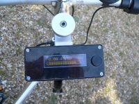
Here's a sneak preview of my handlebar mounted battery/controller/display unit. Originally I was going to make it plug in, but it was too clumsy an arrangement, so I just reverted to a military style multipole connector for the motor/halls/throttle and kept the 25 way D type as a charge connector.

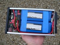
It was a tight squeeze getting two 6S 5 Ah Zippys, a 6 FET Xiechang controller board, a combined soft-start power switch and current/voltage sensor board and an OLED display with the µcontroller that runs all the housekeeping, but it did all fit in the end. Here's a shot of the unit with the front panel removed:

Battery - controller - display -  front.JPG

The 6 FET controller sits under the power switch/sensor circuit board, and is reasonably small, about 1 1/2 times the size of a credit card. It's fitted with IRFB3077 FETs, so is capable of at least 50 A, much more than it's ever going to see on this bike, but it's low enough loss such that it won't even get vaguely warm at the 10 to 15 A I'm planning on using.

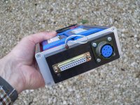
Here's a shot of the base, showing the connectors. The military style one has four 10A DC pins (mil rating, so probably OK for more than double that DC, maybe three times that AC) and 6 5 A rated pins. The 25 pin D type is connected to the balance taps, plus has four pins paralleled to each battery terminal, so I can safely charge with 4 A if need be (each pin of a D type is rated at 1 A).

Battery - controller - display -  base.JPG

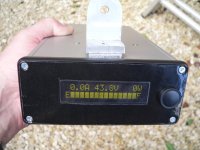
The display is an OLED, with pretty good daylight view-ability. I'm not happy with the shiny front panel, and may change it for something less reflective. The display is run by a small µcontroller (the display and µcontroller combined only cost £10) and this also runs the power switching and housekeeping. The display shows current, voltage and power on the top line and amp hours remaining as a bar graph on the bottom line. Plugging the charger in resets the "fuel gauge" to full. It remembers the capacity remaining even if the battery is pulled out, as it saves it in EEPROM every time it's powered off, just like the CA. It also automatically turns the power off after 3 minutes with less than 300 mA being drawn from the battery. When it shuts off it consumes zero power, not even 1 uA, as it effectively commits suicide by disconnecting the µcontroller power supply on power down. Power on is via the push button on the top, which also acts as a manual power off button. As a crude anti-theft measure the loop of string visible at the base is connected to a tiny neo magnet that operates a reed switch. If this is removed the box cannot be turned on.

Battery - controller - display -  top panel.JPG

I won't now get the bike finished until after I get back from holiday, but will post an update then. The target weight looks achievable for sure, as the battery/controller/display box and all wiring (inc throttle) weighs just 2.15kg.
 
Nice! :) I like the fact your microcontroller shuts itself off.

But your switch to turn it on presumably also closes the circuit that the relay closes once the microcontroller turns on. So, do you have to toggle it on to get the controller on to power the relay that keeps it on, and then toggle off so that the controller can turn itself off later. If that's the case- why not use a momentary switch to turn on the box?

But hey, I might not understand the situation.

I assume it is:


[][][][][][][][][[][][][][][][][][][][][][ ____________________. \_Aswitch_____
PowerInController_______________|________________. \_Bswitch_________|------ucontrolller.

Where Aswitch is the thing to turn on the controller (one way to close that break in the circuit)
And B switch is the relay that the ucontroller controls and keeps closed from when it turns on until it turns itself off.
And the [][][][] are just to get my crude drawing to line up.
 
Kin said:
Nice! :) I like the fact your microcontroller shuts itself off.

But your switch to turn it on presumably also closes the circuit that the relay closes once the microcontroller turns on. So, do you have to toggle it on to get the controller on to power the relay that keeps it on, and then toggle off so that the controller can turn itself off later. If that's the case- why not use a momentary switch to turn on the box?

But hey, I might not understand the situation.

I assume it is:


[][][][][][][][][[][][][][][][][][][][][][ ____________________. \_Aswitch_____
PowerInController_______________|________________. \_Bswitch_________|------ucontrolller.

Where Aswitch is the thing to turn on the controller (one way to close that break in the circuit)
And B switch is the relay that the ucontroller controls and keeps closed from when it turns on until it turns itself off.
And the [][][][] are just to get my crude drawing to line up.

There's no relay, just a couple of paralleled FETs switching the low side power. When these are off no measurable current at all flows from the battery, as their off resistance is up in the many tens of megohms region. The push button is momentary and does two things, it momentarily provides power to the µcontroller to power it on (by turning on power to a voltage regulator via a diode OR arrangement) and also provides a digital input to a µcontroller pin that tells the µcontroller when the button is pressed. Pressing the button from power off turns on the µcontroller and the first bit of code then turns on the FET power switch very quickly (inside 1mS) with a slow turn on to avoid surge as the controller capacitors charge up. This then keeps the controller and display running. Pressing the button again with the power on is detected by the µcontroller as a command to turn the power off, rather than on, and it then saves the capacity remaining in EEPROM and turns off the power, including its own power, by turning off the FET power switch. It will also turn off the FET power switch if it senses that the motor hasn't been run for three minutes, as an auto-power off feature to save accidentally running the battery down by leaving the bike turned on.
 
DAMN NICE JEREMY!! :shock:

I've so far from this skill. Have you done your battery box with your TAIG mill?

And also, I have always been wondering about the vibration on the battery. I always add few layer of anti-vibration foam on it to protect them. But you don't have any. Wouldn't that be a bit dangerous not having anything to protect the pack?
 
cwah said:
DAMN NICE JEREMY!! :shock:

I've so far from this skill. Have you done your battery box with your TAIG mill?

And also, I have always been wondering about the vibration on the battery. I always add few layer of anti-vibration foam on it to protect them. But you don't have any. Wouldn't that be a bit dangerous not having anything to protect the pack?

Thanks for the kind words.

The alloy top panel (under the shiny plastic) was milled out to accept the display and the securing alloy bracket on the back was milled on the Taig, as was the bottom panel where the connectors fit, but the rest of the case was just modded with hand tools from a fairly cheap ready-made Hammond extruded alloy case.

I'm not worried about padding in this case as the packs fit very tightly in this case and have no room to move or vibrate. My other packs do have thin foam around the packs, but they can get banged around a bit, as they don't secure as firmly as this does to the bike. This case is held to the handlebar stem via a rail and a big clamp bolt that locks it tight to the stem, so it can't move at all. Hopefully everything will be so tight that vibration and chafing won't be a problem.

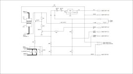
Out of interest, here's my working copy of the schematic for the power switch/voltage regulator/current and voltage sensing stuff that's on that circuit board that's visible:


The µcontroller is actually a re-purposed serial OLED display from here: http://www.techsupplies.co.uk/epages/Store.sf/en_GB/?ObjectPath=/Shops/Store.TechSupplies/Products/AXE133Y

It doesn't need modding, apart from ripping out the original code and rewriting it to do something completely different, but that's easy, as it has a built-in programming connector. The software to programme it is free and once a serial lead is connected you can put whatever code you like into the module, within reason. There are only four spare ports available, as the thing is intended to be just a serial display, but four ports was enough for this job (just.....).
 
jerrysimon said:
Timely to just catch up with this thread. I am also in the UK and have just purchased an Xootr. At the moment it is pretty stock fitted with SRAM X4 derailleur gears. All I have done is to raise the bars and fit Big Apple 406 + 50 tires. This bike is just pure FUN. It is also VERY fast and rigid to ride. The Big Apples smooth out the bumps. I am almost reluctant to "e" it, but am planning on trying one of the new Tongxin Goldant 1.4kg motors. The standard 100mm spaced front dropouts take a motor without any modification (you don't need to open/file the droputs out for the 10mm flats on the motor shaft) and if you use smaller profile nuts and a spacer washers the laws ridges can be left.

I alread have a Brompton M2L-X fitted with one of the Goldant motors.

This shows the differece in size with the exisiting Tongxin and the new Goldant model. Its not much bigger than a dynamo at 100mm diam.

Its early days for these new lightweight motors, but this bike weighs just 11.5kg with the motor fitted. The battery and controller are in the standard Brompton C bag with an umbilical chord that connects it all to the bike.

PS re the discussion on gearing I think an ebike needs a min of two gears. The above Brompton is a stock two speed and the my other Tongxin equipped Brompton (black one shown above) is now fitted with an SRAM A2 which auto changes at 10mph. Both are perfect Cambridge commuters for my work/home ten mile round commute.

Regards

Jerry

Thanks for the reassuring words about the Xootr Swift. I'm pretty impressed with the frameset I've bought from Xootr and am looking forward to getting the bike built and finished. One of the nicest things about this frame is that it accepts standard bike parts in the main, pretty unique for a folder.

I agree about the two gears thing, hence the reason for fitting the Speed Drive to the BB. The ratios are pretty wide (direct drive (50t chain rig, 16t freewheel) and 1.65 over-drive (so equivalent to about an 82t chain ring) but at least this gives the option for a normal fixed speed "low" gear and an acceptably high "top" gear for pedalling fast on the flat.

I ran the Tongxin on my recumbent for a while a few years ago, it was definitely a nice little motor, ideal for gentle assist on a fast bike.
 
Jeremy Harris said:
The alloy top panel (under the shiny plastic) was milled out to accept the display and the securing alloy bracket on the back was milled on the Taig, as was the bottom panel where the connectors fit, but the rest of the case was just modded with hand tools from a fairly cheap ready-made Hammond extruded alloy case.

I'm not worried about padding in this case as the packs fit very tightly in this case and have no room to move or vibrate. My other packs do have thin foam around the packs, but they can get banged around a bit, as they don't secure as firmly as this does to the bike. This case is held to the handlebar stem via a rail and a big clamp bolt that locks it tight to the stem, so it can't move at all. Hopefully everything will be so tight that vibration and chafing won't be a problem.

hmm.. I've always purchases bigger case than my battery to add some foam and protect the pack, but I probably only need to secure it tightly to the case so it can't move. Would be simpler and allow the pack to be smallee.

Also, what you said confirm that I probably need both the hand tool and the taig milling, going to get first the proxxon hand tool and get the taig later when I'll live in a stable location.


And I was thinking for your Xootr, it would potentially be interesting to use a friction drive? Something such as the commuter booster woud be much lighter and still allow you to reach 25mph
 
Friction drive would be a possibility, but probably wouldn't be much lighter than one of these small hub motors. I have the older Tongxin that weighs over 2 kg, but the newer ones from Keyde are only 1.6kg. When you take into account that if you don't have a hub motor you still need a hub and axle, at maybe 0.3kg, then the added weight from the motor is only 1.3kg, not that much heavier than a friction drive and less hassle in terms of allowing things like full mudguards to be fitted and having a neater look.
 
Thanks for the kind words, Joe. I'll post all the details of the box, including the µcontroller code that makes it run, soon, so that anyone who feels so inclined can have a go at making one.
 
Nice work Master Harris, very impressive! Thanks for the updates.
 
you going to open source the micro controller code :p

I enjoy mini folders, trying to figure out how to get good stability in a high powered unit.
I managed to come of one the other week...it hurt.

Turns out now that BMX is an olympic sport 20" gear has gotten a new high grade of competition parts :p
 
Thanks folks. Attached is a simplified schematic that shows the connections to the µcontroller module a bit better. If you download the datasheet for the AXE133Y OLED display (from here: http://www.picaxe.com/docs/axe133.pdf) and take a look at the info on their website here: http://www.picaxe.com/Hardware/Add-on-Modules/Budget-Serial-OLED-Module/ (particularly the pictures) you can probably see that this cheap display has a piggy-backed Picaxe µcontroller driving it. It turns out that they thoughtfully brought the spare ports out on the piggy-back board and fitted a programming header, so that you can just download new code into the thing to re-purpose it.

Here's the simpler schematic, with the Picaxe port numbers (c.0, c.1, c.2 and c.5) added. The code is also attached as a text file within code tags, as the forum doesn't like the .bas extension that the free Picaxe programming software uses. The source code is text anyway, and I've added loads of comments, so you should be able to make sense of it if you're reasonably familiar with simple µcontroller coding (and these chips are about as simple as it gets, as they are designed to be programmed by school kids).

BTW, the current sensor I used was an ACS712, the 30 A version. If you look you'll see I cheated a bit and added a series resistor so I could short the output of this to 0V as a charge reset input (the output normally sits at ~2.5V for zero current). This was just a way of getting an extra signal into the µcontroller, as there were no more spare ports.

Feel free to do as you wish with the code, it may change a bit in future, and I'm sure it could be modded to do some other stuff fairly easily.

Ebike schematic.JPG

Code:
;Feel free to modify and distribute as you wish - consider this open source
;A credit back to the original work would be nice if you find it useful!
;
;Jeremy Harris - August 2012
;
;
;Electric bike power control and power/energy display using 18M2 built in to AXE133Y OLED display
;
;
;The control board that this drives has a FET power switch on the low side plus a Hall effect
;current sensor and potential dividers to measure/detect switched battery voltage.  
;The circuit draws zero current when powered off.
;
;Power off control causes the current capacity value to be stored in EEPROM and then allows the picaxe
;to "commit suicide" by turning off it's own power supply
;
;Power is turned back on by a momentary push button and is then latched on by the picaxe

;The code includes an automatic turn off function.  If no appreciable current is detected for between 2.5 and 3
;minutes the picaxe turns the power off to conserve battery capacity
;
;When the picaxe is powered up with the push button and detects that the battery is being charged
;(using a shorting link on the charging connector) it resets the capacity in EEPROM to the battery fully charged capacity
;
;Due to the word length limit, the maximum allowable battery capacity is 18.2 Ah (65,536 amp seconds)
; 
;This version is set for a battery capacity of 5 Ah (18,000 amp seconds)
;
;

#picaxe 18M2


EEPROM $00, ("E",3,1,1,1,1,1,1,1,1,1,1,1,1,2,"F") 	; store 0 bar (EMPTY) msg in the EEPROM memory
EEPROM $10, ("E",0,1,1,1,1,1,1,1,1,1,1,1,1,2,"F") 	; store 1 bar msg in the EEPROM memory
EEPROM $20, ("E",0,0,1,1,1,1,1,1,1,1,1,1,1,2,"F") 	; store 2 bar msg in the EEPROM memory
EEPROM $30, ("E",0,0,0,1,1,1,1,1,1,1,1,1,1,2,"F") 	; store 3 bar msg in the EEPROM memory
EEPROM $40, ("E",0,0,0,0,1,1,1,1,1,1,1,1,1,2,"F")	; store 4 bar msg in the EEPROM memory
EEPROM $50, ("E",0,0,0,0,0,1,1,1,1,1,1,1,1,2,"F") 	; store 5 bar msg in the EEPROM memory
EEPROM $60, ("E",0,0,0,0,0,0,1,1,1,1,1,1,1,2,"F") 	; store 6 bar msg in the EEPROM memory
EEPROM $70, ("E",0,0,0,0,0,0,0,1,1,1,1,1,1,2,"F") 	; store 7 bar msg in the EEPROM memory
EEPROM $80, ("E",0,0,0,0,0,0,0,0,1,1,1,1,1,2,"F") 	; store 8 bar msg in the EEPROM memory
EEPROM $90, ("E",0,0,0,0,0,0,0,0,0,1,1,1,1,2,"F") 	; store 9 bar msg in the EEPROM memory
EEPROM $A0, ("E",0,0,0,0,0,0,0,0,0,0,1,1,1,2,"F") 	; store 10 barmsg in the EEPROM memory
EEPROM $B0, ("E",0,0,0,0,0,0,0,0,0,0,0,1,1,2,"F") 	; store 11 bar msg in the EEPROM memory
EEPROM $C0, ("E",0,0,0,0,0,0,0,0,0,0,0,0,1,2,"F") 	; store 12 bar msg in the EEPROM memory
EEPROM $D0, ("E",0,0,0,0,0,0,0,0,0,0,0,0,0,2,"F") 	; store 13 bar msg in the EEPROM memory
EEPROM $E0, ("E",0,0,0,0,0,0,0,0,0,0,0,0,0,0,"F") 	; store 14 bar (FULL)msg in the EEPROM memory


symbol current0 	= C.0 ; current sense input 0 (ADC) (also used for capacity reset when shorted to ground)
symbol voltage1 	= C.1 ; voltage sense input 1 (ADC)
symbol poweron 	= C.2 ; power on output 2 (out)
symbol on_off	= C.5	; on/off button sense input 5 (input)
symbol enable 	= C.6	; LCD enable
symbol rs 		= C.7	; LCD RS 


; LCD data pins are on B.0 to B.7


; Supported display bytes:
; 0-7, 8-15	CGRAM characters
; 16-252	normal ASCII characters, according to selected character map table

; Supported command bytes:
; 1		Display clear (leaves cursor position where it is)
; 2		Return cursor to home position (line 1, position 1)
; 128 	sets cursor at first character, first line (128 + x moves to position x)
; 192 	sets cursor at first character, second line (192 + x moves to position x)
; 8 		hides display
; 12 		restore display
; 14 		turn on cursor
; 16 		move cursor left one character
; 20 		move cursor right one character


	SYMBOL display_byte = b0
	SYMBOL loopcounter = b1					;loopcounter is used by "measurementloop" and "charged"
	
	SYMBOL Capacity = w1					;Capacity holds battery capacity remaining in amp seconds (18.2 Ah max, due to 16 bit limit)
	
	SYMBOL Current = w2
	
	SYMBOL Voltage = w3
	
	SYMBOL Averagecurrent = w4
	
	SYMBOL Averagevoltage = w5
	
	SYMBOL zerocurrent = w6
	
	SYMBOL Power = w7
	
	SYMBOL digit0 = b16
	SYMBOL digit1 = b17
	
	SYMBOL digit2 = b18
	SYMBOL digit3 = b19
	
	SYMBOL sampleloopcounter = b20
	SYMBOL msg_no = b21
	
	SYMBOL temp1 = b22					;only used in message display sub-routine, so can be used elsewhere
	SYMBOL temp2 = b23
	
	SYMBOL temp3 = b24
	SYMBOL time_out = b25
	
	SYMBOL Totalcurrent = w13
	
	
	SYMBOL antijittercounter = $1C


init:
	;Set up ports and turn on power
	
	let dirsC = %11000100	; PortC 2,6,7 outputs
	let dirsB = %11111111	; PortB all outputs
	
	high poweron		;turn on power switch
	

	; Winstar OLED Module Initialisation
	; according to WS0010 datasheet (8 bit mode)

	pause 500 			; Power stabilistation = 500ms

	; Function set - select only one of these 4 character table modes
	let pinsB = %00111000 	; 8 bit, 2 line, 5x8 , English_Japanese table
	;let pinsB = %00111001 	; 8 bit, 2 line, 5x8 , Western_European table1
	;let pinsB = %00111010 	; 8 bit, 2 line, 5x8 , English_Russian  table
	;let pinsB = %00111011 	; 8 bit, 2 line, 5x8 , Western_European table2
	
	pulsout enable,1  	; 
		
	let pinsB = %00001100	; Display on, no cursor, no blink
	pulsout enable,1 	

	let pinsB = %00000001 	; Display Clear
	pulsout enable,1
	pause 7			; Allow 6.2ms to clear display

	setfreq m16			; change clockto 16Mhz

	let pinsB = %00000010 	; Return Home
	pulsout enable,1

	let pinsB = %00000110 	; Entry Mode, ID=1, SH=0
	pulsout enable, 1
	
	high rs			; Leave in character mode


	; load custom characters for bargraph display to cgram in display:

		
	let display_byte =64
	gosub display_command
	let display_byte =63
	gosub display_data
	let display_byte =63
	gosub display_data
	let display_byte =63
	gosub display_data
	let display_byte =63
	gosub display_data
	let display_byte =63
	gosub display_data
	let display_byte =63
	gosub display_data
	let display_byte =63
	gosub display_data
	let display_byte =32
	gosub display_data			;load custom character 0 (full block)
	
	let display_byte =72
	gosub display_command
	let display_byte =63
	gosub display_data
	let display_byte =32
	gosub display_data
	let display_byte =32
	gosub display_data
	let display_byte =32
	gosub display_data
	let display_byte =32
	gosub display_data
	let display_byte =32
	gosub display_data
	let display_byte =63
	gosub display_data
	let display_byte =32
	gosub display_data			;load custom character 1 (centre, empty)
	
	
	let display_byte =80
	gosub display_command
	let display_byte =63
	gosub display_data
	let display_byte =33
	gosub display_data
	let display_byte =33
	gosub display_data
	let display_byte =33
	gosub display_data
	let display_byte =33
	gosub display_data
	let display_byte =33
	gosub display_data
	let display_byte =63
	gosub display_data
	let display_byte =32
	gosub display_data			;load custom character 2 (right hand empty)
	
	
	let display_byte =88
	gosub display_command
	let display_byte =63
	gosub display_data
	let display_byte =48
	gosub display_data
	let display_byte =48
	gosub display_data
	let display_byte =48
	gosub display_data
	let display_byte =48
	gosub display_data
	let display_byte =48
	gosub display_data
	let display_byte =63
	gosub display_data
	let display_byte =32
	gosub display_data			;load custom character 3 (left hand end, empty)	 


	;Reset capacity to 5Ah (18,000 amp seconds) if reset link (which shorts the current sense to 0V) is connected at power on
	READADC10 current0, Current
	IF Current < 10 THEN GOTO charged
	
	;read value of Capacity stored in non-volatile memory
	READ $F0, WORD Capacity
			
	;Read averaged supply current over 100 readings to get zero value 
	
	FOR loopcounter = 1 TO 100
	READADC10 current0, Current
	zerocurrent = zerocurrent + current
	NEXT loopcounter
	
	zerocurrent = zerocurrent / 100		;set zero current value at power on
			
	;check for capacity over-range from misreading
	IF Capacity >18000 THEN LET Capacity = 18000
	ENDIF
	
	Totalcurrent = 0
	
	;display starting capacity
	GOTO capacitydisplay


mainloop:

	
	;reset internal time variable to zero
	time = 0
	
	;reset sample loop counter to zero
	sampleloopcounter = 0
		
	
sampleloop:

	;take 64 measurements and sum and divide the results to give average current and voltage
	; it takes ~ 196 mS to do this loop 64 times, so ~ 3mS per iteration
		
	;check push button for power off command
	IF pinc.5 = 1 THEN goto poweroff
			
	FOR loopcounter = 1 to 64
	
	;Take voltage reading using 100k/10 divider on battery (55 V maximum) 1 bit ~ 53.8 mV
	READADC10 voltage1, Voltage
	;at this point Voltage can be 0 to 1023, where 1023 = 55V
			
	;Take current reading using ACS712 sensor. 
	READADC10 current0, Current					
	;At this point Current can be any value between about 512 (~0A) and 1023 (~30A) 1 bit ~ 58.9 mA
	
	;Subtract zero current value obtained during initialisation
	Current = Current - zerocurrent
	zerocurrent = zerocurrent + 500					;temp increase zerocurrent to max reading expected
	IF Current > zerocurrent THEN LET Current = 0			;check for under-run error due to noise
	ENDIF
	zerocurrent = zerocurrent - 500					;return zerocurrent to original value
	;At this point Current can be any value between 0 and ~511 (where 511 = 30.0A)
	
	;add current and voltage  to averagecurrent and averagevoltage, maximum allowable is 65,536
	Averagecurrent = Averagecurrent + Current
	Averagevoltage = Averagevoltage + Voltage
	
	;maximum of 64 times around this loop to stay inside 16 bit overflow on totals
	NEXT loopcounter
	
	;voltage is now 0 to 65472 for 0 to 55 V, current is 0 to 32704 for 0 to 30 A	
	
	;convert current to true average over 30 seconds using number of times around sample loop
	;uses sampleloopcounter as temp counter variable (not used elseswhere for anything useful)
	
	LET sampleloopcounter = sampleloopcounter + 1 						;increment counter every time around sample loop
	
	;Averagecurrent is divided by 109 to bring within range 0 to 300 for 0 to 30.0A
	Totalcurrent = Averagecurrent / 109 + Totalcurrent
		
	GOSUB display
		
	IF time = 30 THEN GOTO capacitydisplay				;check to see if 30 seconds has elapsed, if not go around the loop again
			
GOTO sampleloop


capacitydisplay:
	
	 	
	;Totalcurrent is (amps x 10 x number of times around sampleloop) at this point
	
	;first convert Totalcurrent to amps * 10 over 30 seconds (sampleloopcounter is no of samples)
	Totalcurrent = Totalcurrent / sampleloopcounter
	;Totalcurrent is now in the range 0 to 300
		
	;Totalcurrent = 300 = 30A = 900 amp seconds, so multiply Totalcurrent x 3 to get amp seconds
	Totalcurrent = Totalcurrent * 3
	
	Capacity = Capacity - Totalcurrent
	;Capacity now has capacity remaining in amp seconds, within the range 0 to 18,000				
	
	display_byte = 192						;go to start of second line on display
	gosub display_command
		

	IF Capacity <643 THEN LET msg_no = 0
	gosub msg
	ENDIF
	
	IF Capacity >=643 AND Capacity <1928 THEN LET msg_no = 1
	gosub msg
	ENDIF
	
	IF Capacity >=1928 AND Capacity <3213 THEN LET msg_no = 2
	gosub msg
	ENDIF
	
	IF Capacity >=3213 AND Capacity <4498 THEN LET msg_no = 3
	gosub msg
	ENDIF
	
	IF Capacity >=4498 AND Capacity <5783 THEN LET msg_no = 4
	gosub msg
	ENDIF
	
	IF Capacity >=5783 AND Capacity <7068 THEN LET msg_no = 5
	gosub msg
	ENDIF
	
	IF Capacity >=7068 AND Capacity <8353 THEN LET msg_no = 6
	gosub msg
	ENDIF
	
	IF Capacity >=8353 AND Capacity <9638 THEN LET msg_no = 7
	gosub msg
	ENDIF
	
	IF Capacity >=9638 AND Capacity <10923 THEN LET msg_no = 8
	gosub msg
	ENDIF
	
	IF Capacity >=10923 AND Capacity <12208 THEN LET msg_no = 9
	gosub msg
	ENDIF
	
	IF Capacity >=12208 AND Capacity <13493 THEN LET msg_no = 10
	gosub msg
	ENDIF
	
	IF Capacity >=13493 AND Capacity <14778 THEN LET msg_no = 11
	gosub msg
	ENDIF
	
	IF Capacity >=14778 AND Capacity <16063 THEN LET msg_no = 12
	gosub msg
	ENDIF
	
	IF Capacity >=16063 AND Capacity <17348 THEN LET msg_no = 13
	gosub msg
	ENDIF
	
	IF Capacity >=17348 THEN LET msg_no = 14
	gosub msg
	ENDIF
	
idle_check:

	;Check current and if less than 1 amp second drawn for 5 consecutive times around capacity loop (between 2.5 and 3 minutes) turn power off as a power save measure
	
	IF Totalcurrent < 30 THEN LET time_out = time_out + 1		;check for less than 1 amp second average in past 30 seconds
	ELSE time_out = 0								;reset timeout counter if current is still flowing
	ENDIF
	
	IF time_out = 5 THEN GOTO poweroff					;poweroff saves capacity in EEPROM and turns power off
	
	
GOTO mainloop
	

;*******************************************************************************************************************************


poweroff:

	;save value of Capacity in non-volatile storage for use on next power up
	;Note: EEPROM locations from 0 to 240 ($00 to $E9) are used for fixed message storage, $F0 is next available slot
	WRITE $F0, WORD Capacity
	pause 500
	
	;turn off power
	LOW poweron


END	


;*******************************************************************************************************************************


charged:

	;programme redirects to here if charging link is detected at power on
	
	LET Capacity = 18000			;reset capacity to 5 Ah (18,000 amp seconds)
	
	;save reset value of Capacity in non-volatile storage
	WRITE $F0, WORD Capacity
	
	let display_byte = 128			;set cursor to first digit, upper line of display
	gosub display_command
	
	LET display_byte = "B"
	GOSUB display_data			;display "Battery charged" message on upper line of display
	LET display_byte = "A"
	GOSUB display_data
	LET display_byte = "T"
	GOSUB display_data	
	LET display_byte = "T"
	GOSUB display_data	
	LET display_byte = "E"
	GOSUB display_data	
	LET display_byte = "R"
	GOSUB display_data	
	LET display_byte = "Y"
	GOSUB display_data	
	LET display_byte = " "
	GOSUB display_data	
	LET display_byte = "C"
	GOSUB display_data	
	LET display_byte = "H"
	GOSUB display_data	
	LET display_byte = "A"
	GOSUB display_data	
	LET display_byte = "R"
	GOSUB display_data	
	LET display_byte = "G"
	GOSUB display_data	
	LET display_byte = "E"
	GOSUB display_data	
	LET display_byte = "D"
	GOSUB display_data	
		
			
	FOR loopcounter = 0 TO 14
	let display_byte = 192			;set cursor to first digit, lower line, for "fill up" display
	gosub display_command
	let msg_no = loopcounter
	gosub msg
	
	PAUSE 1000
					
	NEXT loopcounter
	
		
	PAUSE 20000
		
	;turn off power
	LOW poweron
	
END


;*******************************************************************************************************************************

;ONLY SUBROUTINES BELOW THIS POINT
	
;*******************************************************************************************************************************


msg:

	; display message from EEPROM sub routine
	; message number 0-15 must be in msg_no when called
	; uses (alters) temp1, temp2, temp3

	let temp1 = msg_no & %00001111 * 16
							; EEPROM start address is 0 to 15 multiplied by 16
	let temp2 = temp1 + 16 - 1 		; end address is start address + (line_length - 1)
	for temp3 = temp1 to temp2		; for 16 times
		read temp3,msg_no			; read next character from EEPROM data memory into b1
		let pinsB = msg_no 		; output the data
		pulsout enable,1  		; pulse the enable pin to send data.
	next temp3					; next loop
	
RETURN


;*******************************************************************************************************************************

display_data:

	;This sub-routine reads data in display_byte and send it to OLED display
	;it returns after acting on the byte


	let pinsB = display_byte 		; output the data
	pulsout enable,1  			; pulse the enable pin to send data.
	
RETURN


;*******************************************************************************************************************************

display_command:


	low rs 	     				; change to command mode for next character
	let pinsB = display_byte 		; output the data
	pulsout enable,1  			; pulse the enable pin to send data.
	pause 30
	high rs					; back to character mode
	
RETURN
	
	
;*******************************************************************************************************************************
display:

	;check to see how many times display has been called to reduce display character jitter by only changing display every X calls
	;uses temp3 as loop counter but this doesn't have to be kept sacrosant between calls to this routine as it only holds a peeked value within this routine
	
	PEEK antijittercounter, temp3
	IF temp3 = 4 THEN
	
		;Averagevoltage is 0 to 65472 (0 to 55.0V) and Averagecurrent is 0 to 32704 (0 to 30.0A)
		;convert average voltage back to volts x 10
		Averagevoltage = Averagevoltage / 119
		;at this point Averagevoltage can be any value between 0 and 550 for 0 to 55.0V

		;convert averagecurrent back to amps x 10
		Averagecurrent = Averagecurrent / 109
		;at this point Averagecurrent can be any value between 0 and 300 for 0 to 30.0A
	
		;convert Averagecurrent to ASCII
		BINTOASCII Averagecurrent, digit2, digit1, digit0
		IF digit2 = "0" THEN LET digit2 = " "
		ENDIF
		let display_byte = 128							;set cursor to first digit, first line
		gosub display_command
		let display_byte = digit2
		gosub display_data
		let display_byte = digit1
		gosub display_data
		let display_byte = "."
		gosub display_data
		let display_byte = digit0
		gosub display_data
		let display_byte = "A"
		gosub display_data
		let display_byte = " "
		gosub display_data							;display current in format "30.0A_", where _ is a space				
		;last digit is a space at character 133			
		
		;convert Averagevoltage to ASCII
		BINTOASCII Averagevoltage, digit2, digit1, digit0
		let display_byte = digit2
		gosub display_data
		let display_byte = digit1
		gosub display_data
		let display_byte = "."
		gosub display_data
		let display_byte = digit0
		gosub display_data
		let display_byte = "V"
		gosub display_data							;display voltage in format "44.2V"	
		;last digit is "V" at character 138
	
	
		;calculate power and display, range is 0 to 999 W
	
		;Average voltage is 0 to 550, Averagecurrent is 0 to 300
		Averagevoltage = Averagevoltage / 10				;scale down to volts		
		Power = Averagevoltage * Averagecurrent					;range is 0 to 16500 watts x 10 (30A x 55V)
		Power = Power / 10							;scale power down to watts
			
		BINTOASCII Power, temp3, digit3, digit2, digit1, digit0
		;discard temp3 and digit3, only hundreds and below displayed (temp3 is re-used here as a digit that's not displayed)
	
		;remove leading zeros from first two digits
		IF digit1 = "0" AND digit2 = "0" AND digit3 = "0" THEN LET digit1 = " "
		ENDIF
		IF digit2 = "0" AND digit3 = "0" THEN LET digit2 = " "
		ENDIF
		IF digit3 = "0" THEN LET digit3 = " "
		ENDIF
		LET display_byte = digit3
		GOSUB display_data
		LET display_byte = digit2
		GOSUB display_data
		LET display_byte = digit1
		GOSUB display_data
		LET display_byte = digit0
		GOSUB display_data
		LET display_byte = "W"
		GOSUB display_data
		;W is at character position 143 which is 16th position on upper line of display
	
		
		LET temp3 = 0								;reset antijitter loop counter
		POKE antijittercounter, temp3
		
	ELSE
		LET temp3 = temp3 + 1							;increment antijitter loop counter
		POKE antijittercounter, temp3	
	
	ENDIF
	
	;keep these resets here as they are needed to maintain correct averaging of voltage and current
	;reset loopcounter to zero
	loopcounter = 0
	
	;reset averagecurrent drawn over sample period to zero
	Averagecurrent = 0
	
	;reset averagevoltage measured over sample period to zero
	Averagevoltage = 0
	
RETURN

;*******************************************************************************************************************************

;*******************************************************************************************************************************
 
Jeremy Harris,
You got some electric bicycle building skills! I see what you build and I want. If you don't want to go into the electric bicycle building business. Get a partner [Not me]. Design, manufacture, marketing, sales, shipping. You just keep doing what you do and let someone else run the business. Thanks for sharing your knowledge.

Sorry if I hijack your build thread.
 
Jeremy Harris said:
Here's a shot of the base, showing the connectors. The military style one has four 10A DC pins (mil rating, so probably OK for more than double that DC, maybe three times that AC) and 6 5 A rated pins. The 25 pin D type is connected to the balance taps, plus has four pins paralleled to each battery terminal, so I can safely charge with 4 A if need be (each pin of a D type is rated at 1 A).

View attachment 1

I've just noticed you're not using the bullet connectors anymore? Did you replace them with the millitary plug? If so why? :)
 
Sorry for the delayed update to this thread, I've been away on hols for a couple of weeks and only got around to getting the bike rideable today.

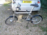
I'm not sure if I'm going to keep the spec as it currently is, though, for two reasons. Firstly the combined battery/controller/display seemed like a good idea, but in practice it looks a bit clunky and could really do with being in front of the bars, rather than behind them. The other issue is the little Tongxin motor. It's fine on the flat, reaching 28mph with ease, but very much lacks hill climbing torque, something that seems more noticeable on the Swift than it did on the recumbent it used to be on. The tall'ish gearing doesn't help, either. Here are a couple of pics of the almost finished bike:

Swift almost finished - Tongxin.JPG

display after first test ride.JPG

The Xootr Swift frame is very nice indeed, nothing like a folding bike to ride at all, as it feels really nice and stable at speed, even on fairly poor road surfaces. The test ride was around 2 miles or so, mainly at speeds of around 20 to 25 mph, and it seems that I used around 32 - 34 Wh, so around 16 to 17 Wh/mile, which is pretty much what I get on the other folder but at lower average speeds. I was peaking at around 950 W, which is way more than the Tongxin should be happy with; the current limit seems to be around 21 A (it's set at 20 A). I've got to tighten the BB up, as the Speed Drive started slipping at the end of the ride, but hopefully that's going to be simple to fix. I can still pedal reasonably comfortably at 30mph in the high ratio (when it wasn't slipping) so the gearing looks reasonable.

I'm toying with the idea of reverting to a seat post mounted battery, sticking the controller in a small sealed box down behind the BB (on top of the side stand mount) and fitting the display in a small handlebar mounted box. If I was to make the battery connector easy to remove, then the bike would be even lighter to lift in and out of the car, as the seat post has to be removed on the Swift to get the rear wheel to fold. On the subject of weight, it's certainly very light. I've not weighed it yet, but suspect that the all up weight (with battery) is around 15kg.

If I do revert to a seat post mounted battery I could go back to my original plan of fitting the rear Bafang BPM motor I have, as I could then just increase the battery voltage to get the speed up (the motor BMS Battery supplied is the wrong winding, and being the useless company they are they won't do anything about their mistake). The bike would be a bit heavier, but the actual weight to lift in and out of the car might be less, with the battery and seat post removed. I may just build the BPM motor up into one of the spare rims I have and see how it goes, anyway, as I'd prefer a bit more hill climbing grunt than the Tongxin can give.
 
Jeremy Harris said:
Sorry for the delayed update to this thread, I've been away on hols for a couple of weeks and only got around to getting the bike rideable today.

I don't recall you being granted leave of abscence from e/s! :twisted:

joe
 
Jeremy Harris said:
I'm not sure if I'm going to keep the spec as it currently is, though, for two reasons. Firstly the combined battery/controller/display seemed like a good idea, but in practice it looks a bit clunky and could really do with being in front of the bars, rather than behind them.

I see what you mean. it would look better at half the height and twice the thickness. Front of the bars would be even better but it would obscure the display - unless you put it out where a bar bag would be, and that would be just silly. :?

I'm toying with the idea of reverting to a seat post mounted battery, sticking the controller in a small sealed box down behind the BB (on top of the side stand mount) and fitting the display in a small handlebar mounted box. If I was to make the battery connector easy to remove, then the bike would be even lighter to lift in and out of the car, as the seat post has to be removed on the Swift to get the rear wheel to fold.

ISTM that the "standard" fold keeps the seat post in place to prevent the frame opening when you lift it. It's also probably a bit awkward to replace the post when you take it completely out - your experience will decide. if that if the case then you would need to hang the battery from the top near the seat rails and have a fixed point on the frame at the bottom incorporating the electrical connection.

But I 'm glad you are liking the Swift. I don't have the need for one myself, but I always thought their website was a fine example to other retailers.
 
Back
Top