Making a 3s parallel pack

pachele

1 µW
Joined
Apr 23, 2020
Messages
3
Hi Guys,

I'm planning to make my first 18650 battery pack for a portable raspberry pi, and have been doing some research. So far here's my progress:

Power calculations of setup:
Raspberry Pi 4
Voltage range: 4.7V - 5.25V
Peak: 3A @ 5V = 15W
Typical: 0.6A @ 5V = 3W

Speaker amp board
Voltage range: 2.5V - 5.5V
Peak: 1.2A @ 5V = 6W
Typical: 0.4A @ 5W = 2W

Screen driver board
Voltage range: (Only specifies 12V and I can't find the specs sheet for this)
Typical: 0.3A @ 12V = 3.7W

Fan
Voltage range: 10.8V - 13.2V
Typical: 0.1A @ 12V = 1.2W

I'd like to run this whole setup for around 6-8 hours, that's a total of 9.9W typical load, which is 59.4Wh - 79.2Wh. So I decided to go with a 3S setup, with 2 of those in parallel, giving ~12V with 75.6Wh using Sony VTC6 18650s:
https://cdn.shopify.com/s/files/1/0697/3395/files/Sony_VTC6_specification.pdf?5816251569019225974

I'd also use a XL4015 DC-DC Buck Converter buck converter to step down the voltage to 5V. http://www.xlsemi.com/datasheet/XL4015 datasheet.pdf
The spec sheet says it can do 5A, which is over my peak requirement of 4.2A, assuming 85% efficiency.

1. I understand that batteries in parallel may cause battery to battery discharge due to differing voltages.
I plan to circumvent this by using a 2A fuse wire to connect the cells, similar to how Tesla wires up their batteries.

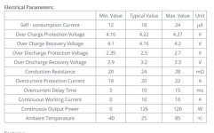
2. I need a BMS to take care of over-charging, over-discharge and over-current.
Plan to purchase this https://www.banggood.com/Seiko-Prot...-p-1107660.html?rmmds=search&cur_warehouse=CN, because it's over-voltage protection is listed to kick in at 4.22V, which is a safe margin as most 18650s recommend going up to 4.25V.

Here's a drawing of my design for the battery pack..
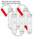
Untitled.png

My problem is mainly with balancing, I understand that since I have batteries in series, it's necessary ensure that cell 2 isn't charged anymore if it has hit ~4.3V even though cell 1 may not be at full capacity since I1=I2. In that case, does anyone know of a 3S BMS that can do balancing?

I've found the HX 3S FL25A-A, that some users mention as able to do balancing, but it's over-voltage protection is 4.35±0.05V, which is pretty high for 18650s based on my research:
LG F1L cutoff voltage: 4.3V
Panasonic cutoff voltage: 4.3V
Sony VTC6 cutoff voltage: 4.25V

HX 3S FL25A-A
https://www.aliexpress.com/item/32817897264.html?af=303127
This reddit thread mentions that it can do balancing:https://www.reddit.com/r/Dynavap/comments/cy8lkn/ih_build_question_accu_bms/
 
First, let's make sure exactly what you are trying to build, before we go on to details that might need to change if you need something different than you expect.

Your title "Re: Making a 3s parallel pack" is either incomplete or incorrect. It implies either you're talking about three cells in series that are paralleled with...something...that is undefined (incomplete), or you actually mean a 3*p* pack, as that is what parallel means. (s is series).

If you do mean both series and parallel, do you mean it to be like in your picture, with 3 in series (3s) and 2 in parallel (2p)?


pachele said:
I'm planning to make my first 18650 battery pack for a portable raspberry pi,
What is the specific voltage input range for this unit? What is it's maximum allowable voltage, and what is the minimum required to operate it?

How much current does this unit take to operate, on average?

How long do you need it to operate at a time, before recharging?

1. I understand that batteries in parallel may cause battery to battery discharge due to differing voltages.
I plan to circumvent this by using a 2A fuse wire to connect the cells, similar to how Tesla wires up their batteries.
The fuse wire does nothing about this.

Cell-level fuse wire is there to prevent a completely shorted cell from draining all the capacity from a large number of parallel cells so quickly that it bursts into flame.

In a 2p pack, unless you had very large capacity very high current capability cells, cell-level fuse wire does absolutely nothing other than add resistance to your pack, degrading it's performance.

It also does nothing at all to prevent slow leakage from draining a parallel group dead, regardless of the number of parallel cells or their capabilities.


most 18650s recommend going up to 4.25V.
Do they? I don't recall that from the (few) datasheets I've seen, but perhaps we're looking at different cells. Which specific cell were you thinking of using?

Remember the datasheet information comes from laboratory specific conditions on single cell testing, and is different from how you would likely wish to use them in the real world for longevity.

Keep in mind that every cell has different characteristics for different needs (or else they would only make one model ;) ). So if you need high current capability, you may use a cell that has that, but has lower capacity. Or you may use a high capacity cell but it can't deliver really high currents. Some are a compromise between the two.
 
A little more general information:

When the batteries are in parallel they self balance. When they are in series you need another way to balance them, like a bms. Balancing your cells is one of the points of a bms.

What you really need to do is make sure all your cells are the same voltage when you start to build your pack, and do not discharge any of the cells when you are building the whole pack. Then, when your pack is built, test the parallel groups to make sure they are all of a similar voltage. Then put the pack on the charger and let them charge and let the bms balance the groups so they are the same voltage to + or - .01v or so. Test the whole pack and individual groups while charging and once again after full charge is achieved.

Also, datasheets are guidelines and standards that should be understood so not to set your pack on accidentally kill it or set it on fire. Understand your specific cells and don't apply any standards to them other then what is specific to them.

For future reference here is the bms specs you linked.
Seiko BMS.JPG

:D :bolt:
 
amberwolf said:
First, let's make sure exactly what you are trying to build, before we go on to details that might need to change if you need something different than you expect.

Your title "Re: Making a 3s parallel pack" is either incomplete or incorrect. It implies either you're talking about three cells in series that are paralleled with...something...that is undefined (incomplete), or you actually mean a 3*p* pack, as that is what parallel means. (s is series).

If you do mean both series and parallel, do you mean it to be like in your picture, with 3 in series (3s) and 2 in parallel (2p)?

pachele said:
I'm planning to make my first 18650 battery pack for a portable raspberry pi,
What is the specific voltage input range for this unit? What is it's maximum allowable voltage, and what is the minimum required to operate it?

How much current does this unit take to operate, on average?

How long do you need it to operate at a time, before recharging?
I should have been clearer about this, added in all the considerations and voltage ranges that led me to the 3s 2 in parallel design in the first post.
amberwolf said:
1. I understand that batteries in parallel may cause battery to battery discharge due to differing voltages.
I plan to circumvent this by using a 2A fuse wire to connect the cells, similar to how Tesla wires up their batteries.
The fuse wire does nothing about this.

Cell-level fuse wire is there to prevent a completely shorted cell from draining all the capacity from a large number of parallel cells so quickly that it bursts into flame.

In a 2p pack, unless you had very large capacity very high current capability cells, cell-level fuse wire does absolutely nothing other than add resistance to your pack, degrading it's performance.

It also does nothing at all to prevent slow leakage from draining a parallel group dead, regardless of the number of parallel cells or their capabilities.
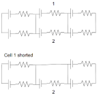
Why isn't a cell-level fuse necessary in a 2p pack?
Untitled2.png
I thought that cell 1 being shorted will lead to cell 2 dumping all it's current into it, as you mentioned.. unless you mean to say that since I only have 2 in parallel, this is not dangerous since the amount of current being dumped is limited to 1 cells output?
most 18650s recommend going up to 4.25V.
Do they? I don't recall that from the (few) datasheets I've seen, but perhaps we're looking at different cells. Which specific cell were you thinking of using?

Remember the datasheet information comes from laboratory specific conditions on single cell testing, and is different from how you would likely wish to use them in the real world for longevity.

Keep in mind that every cell has different characteristics for different needs (or else they would only make one model ;) ). So if you need high current capability, you may use a cell that has that, but has lower capacity. Or you may use a high capacity cell but it can't deliver really high currents. Some are a compromise between the two.
Thanks for the advice on the cells, I went to look into cells even more and realized that I should be using lower amperage cells, since my current load is pretty low, and I can look for higher capacity cells.
 
Ok, why are you worried about shorted cells?

:D :bolt:
 
e-beach said:
Ok, why are you worried about shorted cells?

:D :bolt:

I read that shorted cell is essentially a really small resistor, so that would create a huge flow of current through the shorted cell, causing it to catch fire.
 
That can indeed be true. But if you use high quality cells from known reliable sellers, vs the cheapest deal you can find, it's an unlikely event. Still not impossible, but much less likely than with the cheap stuff (which is too often simply recycled garbage, literally cells that came from dead packs that are already damaged in some way, and/or very old, worn out, etc., and which reuse of is a safety concern).

However, a fuse that would be guaranteed to help in this particular case would also probably blow under normal usage conditions by your device itself. See further below for some numbers that may help you see the issue.

BTW, in order for your cells to be individually fused, you would want to connect them to the nickel tabs only via the fuses, and never to each other. Your drawing, copied below, shows some of the cells being directly paralleled.


pachele said:
Why isn't a cell-level fuse necessary in a 2p pack?
Untitled2.png
I thought that cell 1 being shorted will lead to cell 2 dumping all it's current into it, as you mentioned.. unless you mean to say that since I only have 2 in parallel, this is not dangerous since the amount of current being dumped is limited to 1 cells output?

You can use the fuses if you like, but they're probably not going to do anything unless you size them for fairly low currents.

Some thought experiments with made up numbers, without a datasheet to go from.

Let's say you use cells that normally has around 150-300milliohm internal resistance.

Current thru that cell (in or out) even at full charge voltage of 4.2v would be limited to about 28A, assuming zero voltage drop in the cell during this very high current, and assuming zero resistance in the load. 4.2v / 0.150 ohms = 28A.

Since there would definitely be voltage drop at that current, especially in such a high-resistance cell, the current would be nowhere near that much, because at 28A, the voltage drop across the cell resistance equals the cell voltage. ;) Let's say it is more like half that, or 14A. That only drops half the cell's voltage, or 2.1v, so current can at least continue to flow.... Really it would be different even from this, but...just as a thought experiment.

Then, you have the resistance of the other cell, the "shorted" one, in series with the discharge current. It won't be zero ohms, it's likely to be in the milliohm or higher range. Let's call it 75mohm, or half of what the norm is. So now you have 0.075 + 0.150 = 0.225 ohms in the circuit. Let's say it's 4.2v across that (again, it won't be, it'll be less), so you have 4.2v / 0.225ohms = 18.7A.

Voltage will still exist in the "shorted" cell, too, though lower than ti should be. So let's call it 1v for roundness, so now you only have 3.2v across that 0.225ohms. Now your'e already down to only 14A.

Well, voltage sag at that current might still be a whole volt or more, let's go 1.2v to make that a nice round 2v across the 0.225ohms resistance, and it's down to only 8A already.

Let's say they're as big as 3Ah capacity cells, and they started out full. The 8A current means that if it were sustained, the cell would drain to empty in only 22 minutes. (3A / 8A * 60minutes in an hour) But because voltage drops and resistance changes as the cell discharges, the current will decrease, so really it'll take longer to discharge the cell.

Oh, and I left out that because there is resistnace in the "shorted" cell, the current thru it also generates a voltage across it, so that 8A * 0.75ohm is going to take another 0.6v or so out of the equation, so that's now 2v - 0.6 = 1.4v. So you'd have 1.4v / 0.225ohms = only 6A of current....and agian, this will decrease, probably rapidly from initial flow, to the point where it's little more than your application may actually require. It will decrease even further / faster becuase the cell voltage itself decreases normally in it's discharge curve, which lowers the current, etc. And the cell with a problem will still absorb some charge most likely, faster than it dissipates it, so it's votlage will go up, and again, decreases the current flow thru it.


Since cells aren't even at full voltage very long, and are mostly around 3.7v-ish for almost all of their capacity, it's more likley that a cell-short-failure would occur at or near this voltage, and that significantly alters the currents involved as well. (you can go back up and use 3.7v isntead of 4.2 in all the calculations above, to see what I mean).


At that point, the fuses would probably be blown just by using the device, if they were sized low enough to blow for such an event.

As you can see, it's kind of a complicated process that occurs, because none of these parts are simple resistors, or simple voltage or current sources, and all of the properties are constantly changing and affecting each other.


If you really want to know if it would work, you'd need to test the system under the conditions you'd use it under, and test it by creating a cell failure somehow. Using an already-damaged cell in place of a normal cell mgiht work, but cell failure that actually causes conditions that could lead to a fire is rare enough it might be difficult to create or find a cell damaged enough in the right way to do this. You could simulate it with a literal resistor or wire coil in place of a cell, but it won't have the same conditions a real failure would, becuase of the things described above.
 
Back
Top