Maramusa's 48V Headway PowerTubes Commuter with Mac 8T

maramusa

1 W
Joined
Apr 4, 2011
Messages
58
Location
Australia, WA, Perth, Freo
Have been following the forum for about a year now, and made my first build about 8 months ago, so it's time to show what I have.
I might detail everything I did for a Newbies perspective, Especially the HEADWAY POWER TUBES, as I think it's a pretty easy and solid build that anyone can do.
I wanted it to be very simple, cheap and maintainable, No Welding, Mostly crimping minimal soldering.
I am from Perth(Fremantle) in Western Australia, meaning I say Colour, not Color
Lastly, big thanks to SpinningMagnets and Dogman especially for help and posts, amongst many others
maramusa_bike_1.jpg
and
It is awesome, I am blown away by how good it is....the grin
I use this as my main commuter as I don't have a car and go travelling overseas a lot.
Its' fast, I think due to the 700c wheels, any faster and I don't think the hybrid frame would hold.
I only use it on the road, it plenty fast enough, and goes up basically any hill without pedaling, motor never gets hot!
It rides just as easy as a normal bike, only heavier, I usually always pedal some as i like the speed.
Only real problem I notice is cars don't expect you to be keeping up with them, even if there is a bike lane, and they drift into you...not that I blame them, but get some surprised looks

48V 16s 1P Headway 10AH cells from EV Works (Perth W.A.)
Rear Mac 8T 500/1000W (upgraded with temp sensor) geared motor from cell_man
Wheel Type: 700C Alex DH19 Disc
Controller 12 FET 40A IFRB3077 from cell_man
16S LiFePO4 Type BMS with 40A from cell_man
8sp DNP 11T Freewheel from cell_man
CA-V3 from cell_man

Top speed on flat about 55km/hr (35mph) up to 60km/hr with pedaling
Range about 25-30km with minimal riding
- Max Amps pulled about 36-38A from CA-v3
- Low Volt Cutoff 44V set in CA-v3
- Average W/Hr, from about 250 - 380 from CA-v3
- Use about 6 - 9 Ahr usually between charges
maramusa_bike_2.jpg
maramusa_bike_3.jpg
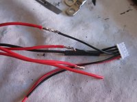
and too many wires (I don't know how everyone else makes there's look so clean)
maramusa_bike_4.jpg

My favourite part is the Headway Battery Packs hereby known as HEADWAY POWER TUBES.
But I will also add the battery pack details to the thread Show Us Your Homemade Battery Housing http://endless-sphere.com/forums/viewtopic.php?f=3&t=12847&start=325
HeadwayPowerTubes_1.jpg
HeadwayPowerTubes_2.jpg
 
Wasn't sure what layout I wanted at first, so I did some trial and error.
I only bought 16s 10AH Headways at first, $18 each from EV Works in Perth, pretty good price and no delivery costs.
but thought I would pretty quick go up to 20AH...which never ended up doing.
Layout_1.jpg
Layout_2.jpg
Layout_3.jpg
I decided to use pine as an internal frame in the triangle using the water bottle threaded holes as mounting points
I also used Solidworks to see if I could squeeze 16s 2p headways in....proved to hard
Layout_8.jpg
Layout_7.jpg
So ended up with this behemoth
View attachment 4
Layout_5.jpg
Layout_6.jpg
but then I saw this beauty, the Faraday Ebike, and got all inspired, I loved the clean lines of the tubes, and got me thinkin... so back to the drawing board
Layout_9.jpg
 
So having decided on tubes, found that PVC pipes at Bunnings were a perfect fit, with enough space for the wires to run along side the cells.
The PVC pipe is perfect as a hard case for the cells, and if each tube held 4s headways as a single pack, I could balance each 4 with a standard 6s Balance charger like the Imax B6.
Then all I need to do is connect each 4s (12v) in series.
Also means when the zombie apocalypse comes, I have a bunch of 12v battery packs to jump start my car.
tried some new layouts
Layout_11.jpg
Layout_12.jpg

Until I ended up with this, it was the best place for centre of gravity and balance, plus leave all the triangle open for the controller , BMS and wires
Layout_13.jpg
 
Next was to work out the wiring
I posted a question on this thread Connecting JST-XH to Lifepo4 http://endless-sphere.com/forums/viewtopic.php?f=2&t=49571#p746819
to work out how to wire so each 4s pack went to the BMS , and could also be connected to the Imax B6 balance charger.

The headways have a pretty strong threaded hole at each end, so I screwed them end to end... there's info somewhere about how much torque they can take, put its a fair bit
HeadwayPowerTubes_3.jpg

I just cut some bolts to use as threaded joiners with a nut in the middle, as you need to be real careful you dont screw too far into the headways,
I put a spring washer and normal washer either side of the balance wire lug
HeadwayPowerTubes_4.jpg
Also, I measured the depth of the thread in the cells, and it is a bit more than the specs state.
HeadwayPowerTubes_5.jpg
the positive side of the cells have a longer thread then the neg as you can see.
I ended up putting some loctite under the nut to stop it turning when doing screwing the thread into the cells tightly, maybe not good idea for conductivity, but all seems fine so far
HeadwayPowerTubes_6.jpg
 
The headways cells fit perfectly snug in the PVC pipe by using some rubber strip about 100mm wide from local rubber store
on either end of the pipe, I put a threaded reducer, so a cap could be screwed on each end. One reducer was glued into place, then other just pushes in
so the cells can be pushed in from one end. I used reducers so the width of the pipe wasn't increased, that was the pipes could be taped together flush.
It easily maintainable, just slide them out , unscrew any cell you want, no solder, no re-crimping.
HeadwayPowerTubes_7.jpg
first tape the wires to the cells, then wrap the rubber around and tape tightly with electrical tape
all the balance wires then run in the gap between the rubber. The cell then push tightly into the pipe, so no sliding around when inside and unscrewing.
HeadwayPowerTubes_8.jpg
a small cutout is needed inside the reducer so the cell end doesn't cut the balance wires as they exit the pipe
HeadwayPowerTubes_9.jpg
out one end come the balance wires and one power lead, the cap has a hole which they all go through
HeadwayPowerTubes_10.jpg
out the other end is the other power lead which connects each 4s tube into series
HeadwayPowerTubes_11.jpg
 
But it sucked having all the 4s tubes joined at both ends in series, it meant to balance a single pack I had to disconnect the power lead at one end,
it was hard to carry 4 tubes joined together and put them on the bike, and water could easily get in the where the power lead lead was at the top on the bike.
So, as I should have done to start with, I instead brought all the balance wires and power leads out one end on the tube, that way i could put a sealed cap on the other end.
Only problem was fitting a thick power lead down the already full tube. This was done by using 4 x 18gauge wires to carry all the current.
I was using 18 gauge auto wires anyway as balance leads so I could charge individual cells with them if needed, so i tried to calculate that 4 of these wires should be able to carry about 30-40 amps.
I crimped the four wires on two yellow auto crimps...so far so good, nothing melted.
HeadwayPowerTubes_13.jpg
HeadwayPowerTubes_14.jpg
HeadwayPowerTubes_16.jpg
I use 45A anderson powerpole connectors for all power leads(enough for the Mac 8T motor which pulls 30-40A), for any Newb, just use them, they are easy and work fine.
Best crimping tutorial I found was here by Dogman http://www.electricbike.com/crimp-anderson/
I didn't buy expensive crimpers, I just followed this tutorial.
In Australia, I bought my andersons from http://www.connector-techals.com.au/, very friendly and helpful
30A
SP1330 - Red with contact @ $0.52
SP1330G4 - Black with contact @ $0.80
45A
1345 - Red with contact @ $0.49
1345G6 - Black with contact @ $0.92
HeadwayPowerTubes_17.jpg
each tubes weighs 2kg (4.4lbs) so a total of 8 kg (17.6lbs). I guess its a bit heavy, but its balanced so well I hardly feel it when riding no power.
View attachment 1
for the balance leads I solder spliced in some JST-XH pigtail leads (from Hobbyking) so I could plug each 4s tube into the Imax balance charge when I felt like it
 

Attachments

  • HeadwayPowerTubes_18.jpg
    HeadwayPowerTubes_18.jpg
    86.8 KB · Views: 2,593
Now all I needed to do was join all the power leads in series, and connect all the balance connectors to the BMS harness.
So I made a nice harness to do the job.
HeadwayPowerTubes_19.jpg
The row of anderson connectors in the middle don't do anything, only there to allow the 4 pairs of power leads to connect and not touch each other.
HeadwayPowerTubes_20.jpg
HeadwayPowerTubes_21.jpg

After some time, I realised that JST-XH connectors are totally sh#t.
HeadwayPowerTubes_28.jpg
They pull out from the weight of the harness, you need to solder splice the pitail which makes the lead big and not flexible, they dont lock, the pins move in the connector and the pins pull out of the connector pretty easy, then a nightmare to fix as the pins are so small it would be a pain to try crimp them so you need to solder on a new connector.....blahhhh, so time to look for better balance wire connectors.
I wanted ones that were small enough to fit through the hole in the threaded end cap on the tube, I wanted to be able to crimp and remove the pins easily and I wanted them to lock together, and be cheap.
After much searching, I FOUND THEM. Don't know what they are called exactly, but I think they are some kind of automotive plug.
For Australia, got then from here http://cgi.ebay.com.au/ws/eBayISAPI.dll?ViewItem&item=120741958348&ssPageName=ADME:L:OC:AU:3160
HeadwayPowerTubes_22.jpg
HeadwayPowerTubes_24.jpg
it really helps to have the correct crimper tool for these
HeadwayPowerTubes_25.jpg
HeadwayPowerTubes_27.jpg
and made a little adapter lead so I can plug into the Imax B6 Balance charge if needed, though I rarely do, the cells stay on balance fine , just use the cell_man bulk charger
HeadwayPowerTubes_29.jpg
 
The last main thing was to work out the Kill Switch, Key, Fuse, and the Pre-charge resistor
I made the key, kill switch and fuse into one, fully water proof unit
KeyKillFuse_1.jpg
plus a momentary push switch for the pre-charge resistor
KeyKillFuse_3.jpg
I use the blank cap (on the velcro) to cover the connector when the key is removed if its raining
KeyKillFuse_2.jpg
KeyKillFuse_7.jpg
The wiring ended up something like this, uses only one 30A fuse between controller and battery, and same fuse between charge and battery.
also has a small 10A fuse incase the pre-charge resistor shorts. pre-charge button only needs a few seconds.
WiringEbike_1.jpg
and lastly a simple box for the BMS
BMS_1.jpg
BMS_2.jpg
 
Back
Top