Hi, just finished repairs on a MW RSP1500-24 SMPS, had some blown Mosfet and VDRs in power factor circuit and a lot of oxidation on chassis and PCBs after it got a lot of rain water during last year. I used RSP1000 schematic for major troubleshooting but I've drawn a partial one for some parts of the circuit as there are quite a lot of differencies.
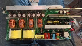
One PCB contains the power factor correction switching (Fets/control IC's/Diodes/Inductors), input filter and rectifier, storage electrolytic caps for HV bus and a small twin 13.5V output smps (TOP244/TX2) for fan and control circuitry on the second PCB.
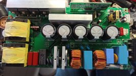
Second PCB contains low voltage buck converter (L900/T900/T901, Q900/901/902/903), Mosfet drivers (IC101/102 UCC27424 and T902/903), control IC UCC3895, current sensing transformer T904, low voltage rectifiers D102/104/106/108. There is a normaly closed thermal cut-off switch on power mosfet heatsink and a fan lock detect and output over voltage crowbar circuit for shut down.
One PCB contains the power factor correction switching (Fets/control IC's/Diodes/Inductors), input filter and rectifier, storage electrolytic caps for HV bus and a small twin 13.5V output smps (TOP244/TX2) for fan and control circuitry on the second PCB.
Second PCB contains low voltage buck converter (L900/T900/T901, Q900/901/902/903), Mosfet drivers (IC101/102 UCC27424 and T902/903), control IC UCC3895, current sensing transformer T904, low voltage rectifiers D102/104/106/108. There is a normaly closed thermal cut-off switch on power mosfet heatsink and a fan lock detect and output over voltage crowbar circuit for shut down.