Meanwell SP-500-48 Repair

Degull

100 W
Joined
Oct 12, 2011
Messages
129
Location
Toronto Canada
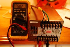
Hi everyone. I bought a supposedly working Meanwell SP-500-48 from ebay very cheap and got taught the age old lesson. You get what you pay for. The power supply showed up dead and it's not worth the shipping to send it back. Thankfully the power supply does not look like it has been previously opened or tampered with. There was no output voltage and the little green LED was not lighting up.

Just to make it easier to follow, there are two boards inside the power supply. I'll refer to the input board where the AC voltage is applied and the output board where the DC voltage is used for output.

http://flic.kr/p/bvqcxK

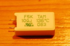
I started poking around with a DMM and appears that input board has a thermal resistor that has gone open circuit. Here is a pic of the offending part.

http://flic.kr/p/bvqcAe

It is a 10 ohm temperature resistor. I removed the temperature resistor and jumpered it to see what would happen. As soon as I applied power the 10 amp fuse on the input board blew. I replaced the fuse and removed all the connections between the output board and the input board. With power applied to just the input board I can measure 374 volts DC on the connector labeled HV. The 10 amp fuse is fine when the output is not connected to the input board and the fuse is blowing when connected to the output board. I am assuming the problem lies in the output board.

Any suggestions would be appreciated!
 
Yep the problem is in the output board. The input board is a PFC + rectifier (nice).

Check for shorted devices, that would be my first bet. Look for the biggest devices on the board on heatsinks and go from there.
 
Are there red wires soldered onto the SVR1 pad? Where do they go? Is the SVR2 jumper in place? You are SURE that big resistor is open?
 
heathyoung said:
Yep the problem is in the output board. The input board is a PFC + rectifier (nice).

Check for shorted devices, that would be my first bet. Look for the biggest devices on the board on heatsinks and go from there.

There are two mosfets k3878 and two fast recovery diodes s20lc30 on heat sinks that I was going to remove and test first. Although I have no idea how to test a fast recovery diode like the s20lc30 (datasheet http://www.shindengen.co.jp/product...30&PHPSESSID=e54d81b8fb2d605c384caedfa94aa482) Not only are the s20lc30 on a heat sink they also have a temperature sensor monitoring the heat sink that they are attached. Any ideas how to test these?

ZOMGVTEK said:
Are there red wires soldered onto the SVR1 pad? Where do they go? Is the SVR2 jumper in place? You are SURE that big resistor is open?

I soldered the red wires going to SVR1. Once I get this puppy working I want to have better control over the voltage output so I've attached a 10 turn 1K Bourns pot.
The SVR2 jumper is in place and the big resistor is definately open. I looked up the datasheet (http://www.tamurathermaldevice.co.jp/e/product_resistor/f5k.html) and it is supposed to be a 10 ohm temperature resistor.
 
why can you not just post up a picture here on the thread?

i cannot follow anything you are talking about and it seems like you already have gone off on a fatal tangent. i doubt if anything can be done to help you recover.

what does it mean when you say you disconnected the front end from the back end? why remove the parts until you have some idea of what is bad?

it seemed originally like it had just blown the ICL, but it doesn't seem like you know what that is or what it does.

it is hard enuff to help someone else diagnose stuff, but this is all totally blind, and doesn't relate to anything i understand about the SMPS.
 
I'm not sure how to post a picture in the thread. The links in the first post are to a flickr account where I have uploaded the pictures. My "fatal tangent" as you call it has led me to find a couple of shorted Mosfets on the output board.

dnmun said:
why can you not just post up a picture here on the thread?

i cannot follow anything you are talking about and it seems like you already have gone off on a fatal tangent. i doubt if anything can be done to help you recover.

what does it mean when you say you disconnected the front end from the back end? why remove the parts until you have some idea of what is bad?

it seemed originally like it had just blown the ICL, but it doesn't seem like you know what that is or what it does.

it is hard enuff to help someone else diagnose stuff, but this is all totally blind, and doesn't relate to anything i understand about the SMPS.

There are two Toshiba 2SK3878 mosfets mounted to a heatsink just before the DC output. I removed the mosfets and tested them with DMM. They are shorted between the gate source and drain. With the mosfets removed,I connected everything back together and plugged the unit into the wall. The fuse is no longer blowing open. Fingers crossed, I'm going to order and install some new mosfets. Hopefully it's a simple as that and the power supply will be operational again.
 
not being facetious, just for future reference:


It's one way to upload them. [click my .png and i have a screenshot]


But I agree with you, that it's just if not more easy to go to your flickr link. Best, though, would be to embed the image.
 

Attachments

  • meanwell.png
    meanwell.png
    20.4 KB · Views: 1,061
Thats what I would have expected - shorted devices.

When you replace them, don't just throw the power on, put a 75W incandescent light globe in series with the mains - it will glow brightly for a second as your caps are charged, and should dim down a lot. Put a DMM on the output, check that it is correct.

If the bulb stays bright, keep looking for shorts. You havn't found them all yet!

If the bulb pulses regularly, and/or the supply chirps, you are having issues with protection - over-voltage or over-current.
 
Kin said:
not being facetious, just for future reference:


It's one way to upload them. [click my .png and i have a screenshot]


But I agree with you, that it's just if not more easy to go to your flickr link. Best, though, would be to embed the image.

I'm going to try that. Thanks so much!

heathyoung said:
Thats what I would have expected - shorted devices.

When you replace them, don't just throw the power on, put a 75W incandescent light globe in series with the mains - it will glow brightly for a second as your caps are charged, and should dim down a lot. Put a DMM on the output, check that it is correct.

If the bulb stays bright, keep looking for shorts. You havn't found them all yet!

If the bulb pulses regularly, and/or the supply chirps, you are having issues with protection - over-voltage or over-current.

I would have never thought about trying a light bulb in series. Brilliant, thank you for the suggestion, I'm going to give that a try before power is applied.
 
No problems, I used to do a lot of smps repair and it really saves on the laundry bills when something explodes in your face :mrgreen:
 
I've never seen that model before.

Yes, the FETs and diodes typically fail by shorting.

Whatever was driving the FET gate can also blow when the device shorted, so there's a chance just replacing the big parts won't be enough. I've fixed quite a few supplies though, and about 8 out of 10 times the driver parts survive.

Light bulb is a great idea.
 
It lives!

Mean3.jpg

I replaced the two faulty mosfets and placed a jumper wire where the faulty temperature resistor was installed. I haven't had a chance to load it up yet so the real test will be when I try charging a battery with it.

For anyone else with the same problem with one of these power supplies in particular, the original Toshiba 2SK3878 mosfets are no longer available but 2SK2968 are direct replacements. They are available at Digikey or Mouser. The temperature resistor is not easy to source so I'll leave the jumper wire in place for now.

The next problem is trying to find the OVP point so I can install Fetcher's Mini Meanwell limiter board. I've searched the forum and I can't find much info on this power supply. Is there anything in particular that might help me locate a OVP point?
 
Take a picture of the board.
The OVP point will be close to where the voltage adjustment pot connects.

The resistor you want is typically called a NTC thermistor.
Here's one from Mouser:
http://www.mouser.com/ProductDetail/EPCOS/B57364S100M/?qs=0ZUpllj3bsbbT%2bFz1uLThA==

I'm not sure if this one has a high enough current rating. It might be possible to parallel two.
This is supposed to limit the inrush current when you plug the supply into the wall, then heat up and drop its resistance.

Without it, you could possibly trip the wall circuit breaker and/or stress the input diodes and cap.
 
i kinda thought it was the ICL, but he never posted up a picture where we could see. i have a buncha big ones here i usually sell to people who blow theirs in the vpower chargers.

i am really surprised that the mosfets blew up. if the ICL had blown, then they would not have seen any current enuff to blow them up. imo
 
fechter said:
Take a picture of the board.
The OVP point will be close to where the voltage adjustment pot connects.

The resistor you want is typically called a NTC thermistor.
Here's one from Mouser:
http://www.mouser.com/ProductDetail/EPCOS/B57364S100M/?qs=0ZUpllj3bsbbT%2bFz1uLThA==

I'm not sure if this one has a high enough current rating. It might be possible to parallel two.
This is supposed to limit the inrush current when you plug the supply into the wall, then heat up and drop its resistance.

Without it, you could possibly trip the wall circuit breaker and/or stress the input diodes and cap.

The original thermistor installed is rated at 3 amps according to the manufacturer's data sheet. The one you recommended is 7 amps so it should do fine. Thanks! Here is a picture of the dead thermistor:

Mean1.jpg

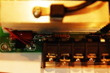
The next picture is the front of the board where the voltage adjustment pot lives. I replaced the original voltage pot with a 10 turn Bourns pot and you can see the three red wires running to it.

Mean4.jpg

The SRV2 pads are on the opposite side of the board and are not shown.
 
It's a little hard to see in the pic, but if you look at where the pot attaches, it looks like there are two traces headed under the terminal strip. It might be nice to know where they go to. There could be traces on the other side of the board too.

Typically, one side of the pot goes to ground. You can test this with an ohmmeter to the negative output terminal (power off!).

The other side goes to a fixed resistor. You need to find this resistor. The side of the resistor opposite the pot connection should be your OVP spot. This you can test with power on, should be 2.5V or slightly less.
 
The joy of a working power supply was short lived. I found the OVP point in the middle of the board. It was easy to find with your instructions and measured exactly 2.48V. That was short lived because soon after I found the OVP point. the OVP voltage dropped to around 1.8volts the output voltage is now being limited to 52V.
When I first replaced the mosfets I could vary the voltage between 38 to 60 volts. I believe the OVP was working properly because I could watch the voltage drop suddenly if I kept turning the pot past 60 volts. Turning the pot back down allowed it to act normal and I could adjust the voltage between 38 to 60 volts again.
Now for some reason the output is being limited to 52 volts and the OVP stays around 1.8 V. Not sure what I did other than poke around the board with my meter measuring voltages.

:oops:
 
Hmm... not sure what's going on there. Anytime the OVP tries to go over 2.5v, the regulator backs off the output to keep it at 2.5v. Something else must be limiting the output.
There is also usually some kind of overcurrent protection on both the primary and secondary side that work on separate circuits. One of these may be kicking in for some reason.
 
You might try running it for a few minutes and see if anything is getting hot. Check the ouput caps, the big transistors and diodes, and the transformer (check temps with power off!).
 
Hi. Finally had a chance to spend some time with the power supply. I let it sit powered on for about 20 minutes and then poked around looking for hot components. There doesn't seem like anything is getting unusually warm. The output voltage is steady and the power led stays on bright.
When I fried the supply, I was poking around the OVP resistor, the voltage on the regulator was 2.48 V and then climbed up to as high as 8 volts. I'm wondering if I just fried the regulator with the DMM while measuring the legs? I'm going to remove the regulator and see how the output voltage behaves.
Thanks for the guidance.
 
Can you tell if the OVP point is going to a XX431 type 3 pin regulator or does it go straight to the PWM chip?
Can you read the number off the PWM chip? Most I've seen use a TL494.

No heating is a good sign.

Poking with the meter shouldn't hurt anything unless the probe accidently shorted something.
 
I don't have the power supply in front of me but I did pull the regulator off before I went to bed last night. It's a AS431 regulator. I powered up the supply with the regulator removed and it went straight into protection mode. I can tell it is protecting itself because the power led is flashing quickly and the voltage stays at a constant 48 volts. I noticed it did the same thing when it was working properly and I turned the voltage up past 60 volts.

On my way home I'm going to see if I can get a tl431 regulator to replace the AS431 regulator that was installed.
 
It lives again!

I replaced the AS431AZ-E1 regulator with a TL431CLP which has inferior tolerances. The local electronics shop surprised me that they had any TL431 regulators in stock. It is finally working like it did before I broke it the last time :roll: I can now vary the voltage between 38-60V again!!
 
Excellent!

Don't worry about the tolerances. That's what the voltage adjustment pot is for. :wink:
 
Back
Top