
You are using an out of date browser. It may not display this or other websites correctly.
You should upgrade or use an alternative browser.
You should upgrade or use an alternative browser.
Modular, Multi-Platform, 300A ESC
- Thread starter badgineer
- Start date
owhite
100 W
- Joined
- Aug 3, 2020
- Messages
- 285
My last order for 10 boards was $232 USD not including shipping.
Then you'll need:
Then you'll need:
- 18 FETs (see this page for suggestions [LINK]
- some caps
- DCDC converter for 12v (example: PQDE6W-Q110-S12-D)
- DCDC converter for 5v (example: XP power VR05S05)
- headers (example: 929850-01-20-10)
- the cheapest ST-LINK2 programmer you can find on ebay or amazon
- and a pill.
Last edited:
badgineer
10 W
Hi.I will then need the fets and a pill
have I missed anything ?
What owhite said
")
and i think its necessary to stress the "some caps" part - you need a few thousand uF, depending on the max phase amps you want to push
oh and thick cables and banana plugs or whatever high amp connectors you like
also, the F405 pill is also jlcpcb ordered, and actually iirc more expensive than the "main" esc board.
btw - please read the docs, me and owhite (especially owhite) really invested time in them. should answer a lot of your questions
also mxlemming had a post with a lot of helpful info at the very beginning of the thread.
br,
Hi,
Finally, I came to the conclusion that I have to reconsider using my existing STM32F411 pill instead of building a F405 one.
So, I came back to Lemmy's instructions explained above and compiled branch "FW_ADC_sampling" for F411 with 0 errors and 221 warnings, starting from a clean install of STM32 IDE.
Lemmy, when you did the compilation for the F411, did you also got these warnings ?
Here is a few ones:

Thanks for your help.
Finally, I came to the conclusion that I have to reconsider using my existing STM32F411 pill instead of building a F405 one.
So, I came back to Lemmy's instructions explained above and compiled branch "FW_ADC_sampling" for F411 with 0 errors and 221 warnings, starting from a clean install of STM32 IDE.
Lemmy, when you did the compilation for the F411, did you also got these warnings ?
Here is a few ones:
Thanks for your help.
mxlemming
100 kW
- Joined
- Jul 17, 2020
- Messages
- 1,122
No idea where the name Lemmy came from. The only Lemmy I know is the lead singer for the band Motorhead, may he RIP. If you mean me, then no I don't usually get hundreds of warnings, but I rarely use the f411 project.
I suggest using the more recently updated branch master. The FW_ADC_sampling branch must be someone like 10 months old now. I would also err on the side of f405 pull since netzpfuscher and I routinely work on that one.
[ QUOTE="Haibiker, post: 1775751, member: 80307"]
Hi,
Finally, I came to the conclusion that I have to reconsider using my existing STM32F411 pill instead of building a F405 one.
So, I came back to Lemmy's instructions explained above and compiled branch "FW_ADC_sampling" for F411 with 0 errors and 221 warnings, starting from a clean install of STM32 IDE.
Lemmy, when you did the compilation for the F411, did you also got these warnings ?
Here is a few ones:
View attachment 340196
Thanks for your help.
[/QUOTE]
Sorry for the mistake Lemmy/mxlemming.
I reloaded the main branch and then got 0 errors and 0 warnings

Now I have to understand where and how to customize the code according to the motor...
I really would like to stick to the F411 because this pill is easy to get.
I reloaded the main branch and then got 0 errors and 0 warnings
Now I have to understand where and how to customize the code according to the motor...
I really would like to stick to the F411 because this pill is easy to get.
mxlemming
100 kW
- Joined
- Jul 17, 2020
- Messages
- 1,122
You just have to plug in the usb, connect to the serial port with putty or mobaxterm and type anything then enterSorry for the mistake Lemmy/mxlemming.
I reloaded the main branch and then got 0 errors and 0 warnings
View attachment 340233
Now I have to understand where and how to customize the code according to the motor...
I really would like to stick to the F411 because this pill is easy to get.
Then type get and it gives you all parameters
set abcdefg 123 sets it
There's measure which sometimes works but you're best off entering the parameters Rphase Ld and flux manually. It's just less hassle that way if you know them.
Then input options
Curr max
Set the ADC upper and lower thresholds...
Then there's options for openloop, sensorless, startup options...
hilllzofvalp
10 mW
- Joined
- Dec 25, 2010
- Messages
- 20
reserved
Last edited:
thepronghorn
1 kW


badgineer
10 W
Hi.@owhite I just ordered 5pcs of the 1.11 F405 pills, and jlcpcb is complaining that the outline of the board is "shaving the trace" and want to expand the outline by 0.4mm. Have you ordered this version of the board yet?
A guy from Germany I know ordered a set on 24 September and they did not complain at that time.
However that batch is not tested yet so cant say if it works or not.
Expanding the outline seems like a safe enough thing to do though
Br,
A-DamW
100 W
@thepronghorn , I ordered 5pc of v1.11 pill from JLC on 2023-09-08, no problem, however, I used the MANUFACTURE files in this folder:
F405_pill/F405_pill_V1.11/MANUFACTURE at main · davidmolony/F405_pill
The only thing I had to modify(remove) was component U1 (stm32f405rgt6) in the BOM and POS files, as it was not in stock at the time.
JLC has ~600 stm32f405rtg6 in stock right now!
I just now ordered 5pc v1.11 with stm32f405rgt6 complete, crossing fingers it all goes well and the boards test good when they arrive.
Last edited:
owhite
100 W
- Joined
- Aug 3, 2020
- Messages
- 285
Sorry for the late reply. Yes, I have ordered these and like A-DamW I did not have an issue. I also have had the experience when JLC has found problems in boards that I have submitted before and there were no complaints. Agree with badgineer -- making that change seems fine to me.@owhite I just ordered 5pcs of the 1.11 F405 pills, and jlcpcb is complaining that the outline of the board is "shaving the trace" and want to expand the outline by 0.4mm. Have you ordered this version of the board yet?
thepronghorn
1 kW
Thanks for the replies. My boards shipped yesterday, so hopefully I'll have some working controllers in the next couple weeks, although mine are going to look a lot different from normal MP2s.
owhite
100 W
- Joined
- Aug 3, 2020
- Messages
- 285
FLASH MESC AND USE THE STM32CUBEIDE DEBUGGER
Greetings people. I have made two video tutorials:
Documentation for Video1 is here: [LINK], Video 2 documentation is here: [LINK]
Topics for the videos include:
The MESC github branch for the tutorials is here: [LINK]
Greetings people. I have made two video tutorials:
Documentation for Video1 is here: [LINK], Video 2 documentation is here: [LINK]
Topics for the videos include:
- Loading MESC into STM32CubeIDE
- Configuring MESC code
- Flashing code to the F405 pill
- Running the STM32CubeIDE debugger
- Using the MESC terminal
The MESC github branch for the tutorials is here: [LINK]
Last edited:
lepierrefoe
1 µW
Hi, David Molony.
What's about l431 branch,any issues?
It has minimal ram usage 8.78kb and 62k flash(CubeIde).
Is it possible to dump lcd, fonts, etc to limit ram usage to 6-7kb max ?
ARM v8m aproach , cortex m23, 33.
What's about l431 branch,any issues?
It has minimal ram usage 8.78kb and 62k flash(CubeIde).
Is it possible to dump lcd, fonts, etc to limit ram usage to 6-7kb max ?
ARM v8m aproach , cortex m23, 33.
Last edited:
mxlemming
100 kW
- Joined
- Jul 17, 2020
- Messages
- 1,122
I haven't tested l431 for ages, last time i did it worked well up to about 30khz.Hi, David Molony.
What's about l431 branch,any issues?
It has minimal ram usage 8.78kb and 62k flash(CubeIde).
Is it possible to dump lcd, fonts, etc to limit ram usage to 6-7kb max ?
ARM v8m aproach , cortex m23, 33.
The l431 is a good choice because the ADC is much better than the f405 one so it actually runs smoother but its not supported by the terminal. Firstly because there's no usb but mainly because we just haven't bothered to take the time porting the terminal to a niche target. It requires remapping the flash and doing memory writing things specific to the MCU which is a pain.
You can still set it up using the defaults and it'll work fine.
Its Cortex m4 not m33 or m23 or whatever you're talking about.
lepierrefoe
1 µW
David Molony, there is STM32L432KCU6 for my prefered stamp( must be Revised for 3 shunt topology).Small size is prefered.
Sorry cortex m23 is not sufficient(no math).
Gd32 was ment due to low price and high avalaibility.
Defenitely m4.
Trying to implement similiar to EBICS_FOC.
USB is not important at all.
Sorry cortex m23 is not sufficient(no math).
Gd32 was ment due to low price and high avalaibility.
Defenitely m4.
Trying to implement similiar to EBICS_FOC.
USB is not important at all.
owhite
100 W
- Joined
- Aug 3, 2020
- Messages
- 285
Hello people,
I'm please to report on a new open source version ESC. This board uses NVMTSC4D3N15MC MOSFETs but still is a MP2:
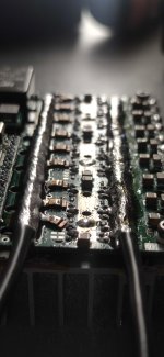
Assembly. To construct, I ordered the board from JLCPCB complete with the NVMTSC4D3N15MC MOSFETs. Everything was loaded on the board except the through-hole parts. Before adding through-holes, smear solder paste on the flat bus bars, put in place then drop on hot plate with busbars facing down. Busbars are on the bottom side of the board, you cant really see the solder melting, so put a blob of solder paste on the top side and wait til the board is hot enough to melt the paste. Switch off hot plate and let it cool. To solder in the tombstone shaped phase connectors, you have to file the tabs a bit to fit into the slots on the board. Then carefully use a butane torch to heat the tombstones with paste between their base and the board. Finally solder in through-hole components, and the assembly should look like this:

Refer to this page for board testing: [LINK] most of the continuity and resistance checking still apply to this MP2 version.
Firmware. Theoretically this board will work with the VESC but has not been tested so far. You'll have to ask some nice person to make you the correct header files for that firmware. So use MESC! There's a tutorial, using MESC and the open source F405 pill. This video is fine for most steps, just note to run on MESC, this board has a different vsense voltage divider than previous MP2-ESCs, requiring you to set these variables in MP2_V0_1.h:
Cooling. The NVMTSC4D3N15MC MOSFETs are basically a millimeter thick and red hot pin heads probably dissipate heat faster than these things. They get hot fast. Other strategies may work but I use a laser cut chunk of aluminum [LINK] with the thermal pad. No thermal grease was used. A pic of it assembled: [LINK]. One important new design element is that the MOSFETS are now on the top region of the board exposing the FETs so at least in my case it is easier to expose the heatsink to the forward airflow on my bike. Airflow is imperative. This graph shows it's performance when the MOSFETs are bare, covered with a heatsink, and when a fan is pointed at the heatsink. The good news is it looks like running continuously at 70A, 100V is no problem with proper cooling:

Performance. After running some motor testing on the bench it was time to take the MP2-DFN out on the bike. Field testing was done on this platform [LINK], which has a QS165v1.0 running at 18S. The MP2-DFN controller was running MESC firmware on a F405 pill.

Where motor RPM = ehz * 60 / polepairs, and translates to roughly 57MPH (91KPH). Note this was cheating a little, I was on a slight downhill grade. TMOS refers to temp (this was with bare mosfets, no heatsink), phaseA is phase amps, iqreq basically refers to when I have applied the throttle.
Acknowledgements. I did not design this board. I adopted it from the MP2-ESC design. This board absolutely would not have been possible without the intellectual work of the MP2-ESC team. I gratefully offer many many thanks to:
Enjoy this new version of the MP2 and feel free to post questions!
I'm please to report on a new open source version ESC. This board uses NVMTSC4D3N15MC MOSFETs but still is a MP2:
- Designed to run 300A at 150v (so far only tested at 100v)
- Fully compatible with VESC using the STM32F405 pill
- Cheap to order -- manufacturing files ready to upload to JLCPCB
- Compact design, great for ebikes / medium-large electric scooters
- No more TO-220s, no more wonky heatsinks
- Updated bulk MLCCs to 250v rating
- 12v DC-DC and 5v DC-DC flipped to underside of the board
- Easy to order busbars for assembly and heatsinks for assembly
- Main repository: [LINK]
- Github branch for this release: [LINK]
- JLCPCB files: [LINK]
- Circuit diagram: [LINK]
- 160VDC 470uF caps, MFR#: EKXJ161ELL471MMN3S
- 20 pin headers: MFR# 929850-01-20-10
- 12VDC-DC converter: MFR# PQDE6W-Q110-S12-D
- 5VDC-DC converter: MFR# VR05S05
- Thermal pad material: COH-4000LVC-200-05
- Consider ordering laser cut sendcutsend.com busbars and heatsinks. DXF files: [LINK]
Assembly. To construct, I ordered the board from JLCPCB complete with the NVMTSC4D3N15MC MOSFETs. Everything was loaded on the board except the through-hole parts. Before adding through-holes, smear solder paste on the flat bus bars, put in place then drop on hot plate with busbars facing down. Busbars are on the bottom side of the board, you cant really see the solder melting, so put a blob of solder paste on the top side and wait til the board is hot enough to melt the paste. Switch off hot plate and let it cool. To solder in the tombstone shaped phase connectors, you have to file the tabs a bit to fit into the slots on the board. Then carefully use a butane torch to heat the tombstones with paste between their base and the board. Finally solder in through-hole components, and the assembly should look like this:
Refer to this page for board testing: [LINK] most of the continuity and resistance checking still apply to this MP2 version.
Firmware. Theoretically this board will work with the VESC but has not been tested so far. You'll have to ask some nice person to make you the correct header files for that firmware. So use MESC! There's a tutorial, using MESC and the open source F405 pill. This video is fine for most steps, just note to run on MESC, this board has a different vsense voltage divider than previous MP2-ESCs, requiring you to set these variables in MP2_V0_1.h:
#define R_VBUS_BOTTOM 3300.0f
#define R_VBUS_TOP 150000.0f
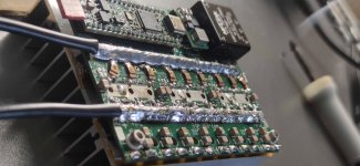
Cooling. The NVMTSC4D3N15MC MOSFETs are basically a millimeter thick and red hot pin heads probably dissipate heat faster than these things. They get hot fast. Other strategies may work but I use a laser cut chunk of aluminum [LINK] with the thermal pad. No thermal grease was used. A pic of it assembled: [LINK]. One important new design element is that the MOSFETS are now on the top region of the board exposing the FETs so at least in my case it is easier to expose the heatsink to the forward airflow on my bike. Airflow is imperative. This graph shows it's performance when the MOSFETs are bare, covered with a heatsink, and when a fan is pointed at the heatsink. The good news is it looks like running continuously at 70A, 100V is no problem with proper cooling:
Performance. After running some motor testing on the bench it was time to take the MP2-DFN out on the bike. Field testing was done on this platform [LINK], which has a QS165v1.0 running at 18S. The MP2-DFN controller was running MESC firmware on a F405 pill.
Where motor RPM = ehz * 60 / polepairs, and translates to roughly 57MPH (91KPH). Note this was cheating a little, I was on a slight downhill grade. TMOS refers to temp (this was with bare mosfets, no heatsink), phaseA is phase amps, iqreq basically refers to when I have applied the throttle.
Acknowledgements. I did not design this board. I adopted it from the MP2-ESC design. This board absolutely would not have been possible without the intellectual work of the MP2-ESC team. I gratefully offer many many thanks to:
- mxlemming for his infinite patience, mentorship, MESC code, and help with testing
- badgineer for assistance with circuit design, part selection, support and original MP2-ESC design
- netzpfuscher for the MESC terminal
Enjoy this new version of the MP2 and feel free to post questions!
Last edited:
kubark42
1 W
- Joined
- May 15, 2020
- Messages
- 61
Looks very nice. Could you clarify which of the amps you're testing at are battery or phase amps? I'm guessing the 70A continuous is for the battery, right? And the last graph seems to show 150A phase looks sustainable? And the 300A limitation is phase amps, not battery amps, right? Or am I misreading?Hello people,
I'm please to report on a new open source version ESC. This board uses NVMTSC4D3N15MC MOSFETs but still is a MP2...
owhite
100 W
- Joined
- Aug 3, 2020
- Messages
- 285
All references to amperage in the post are phase amps.Looks very nice. Could you clarify which of the amps you're testing at are battery or phase amps? I'm guessing the 70A continuous is for the battery, right? And the last graph seems to show 150A phase looks sustainable? And the 300A limitation is phase amps, not battery amps, right? Or am I misreading?
pan_sattan
1 µW
Hi all,
I am looking for something which will drive this kind of motor below....
Is that the right thing? Or should I build something else?
Motor Eagle Power EA120 65KV
Main aim is to lift at least 30kg with that motor. For project will be used 24S Lifepo4 batteries
I am looking for something which will drive this kind of motor below....
Is that the right thing? Or should I build something else?
Motor Eagle Power EA120 65KV
Main aim is to lift at least 30kg with that motor. For project will be used 24S Lifepo4 batteries
mxlemming
100 kW
- Joined
- Jul 17, 2020
- Messages
- 1,122
This is a very reasonable matching of motor and ESC. Unsure how well the eagle power motor will respond to FOC. Some of the outrunner motors work really well and others experience issues at high currents. But hardware capability wise it's a good match.Hi all,
I am looking for something which will drive this kind of motor below....
Is that the right thing? Or should I build something else?
Motor Eagle Power EA120 65KV
Main aim is to lift at least 30kg with that motor. For project will be used 24S Lifepo4 batteries
pan_sattan
1 µW
I just want to be sure before I start... so that will manage lets say 7000rpm of that 65kv motor on 24S battery? this motor is maybe more construct for BEMF, not FOC... is there any method, how to analyze if it will work? I already bought that motor...
mxlemming
100 kW
- Joined
- Jul 17, 2020
- Messages
- 1,122
Yes it will be able to drive it to that speed. Whether it's sensible to spin that motor that fast... I doubt it. It will be absolutely screaming and will get hot very fast regardless of the control method. 28pp implies 98kerpm, 1633eHz. That's extremely fast for iron laminations.I just want to be sure before I start... so that will manage lets say 7000rpm of that 65kv motor on 24S battery? this motor is maybe more construct for BEMF, not FOC... is there any method, how to analyze if it will work? I already bought that motor...
Last edited:
Hello, I think I built the latest version v0.6 and I have a problem with the configuration file. The voltage measurement resistor values have changed to 360k and ~7900k. The mosfets I used were mdp10n027. Capacitors 4x 2000uF 100V nichicon. Everything works on small drone engines, but unfortunately not on larger ones. I set the dead time to 250ns. Is there an updated description of the PCB pins somewhere? Unfortunately, I don't currently have an oscilloscope to check the gates.
Attachments
Similar threads
- Replies
- 222
- Views
- 27,100