Motor Smoothness: FOC vs. Six-Step BLDC

Delancy7

1 mW
Joined
Apr 3, 2024
Messages
14
Location
California
I've got a Hudson 2310P motor that runs very smoothy on my motor controller when running my dad's FOC code, but when I run the same motor using his six-step BLDC code (the motor has both a six-step Hall encoder and a quadrature encoder--the FOC code uses the quadrature encoder and the BLDC code uses the Hall encoder) the motor makes much more noise and doesn't seem run as smoothly at the same RPM as when running with the FOC code. I'm trying to understand why this is the case.

Commutating the motor every 60 degrees won't be as smooth or as quiet as FOC using a much higher resolution sensor, but I've used other motors on the same controller with the same code and the difference was hardly noticeable. Is it possible that I'm seeing this difference with the Hudson motor because it has sine windings rather than trapezoidal windings? Can that make that much of a difference?

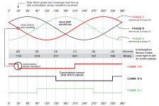
This what the back EMF looks like (from the Hudson user manual):
Screenshot 2024-04-08 142950.png
 
Last edited:
If you're using typical 3-hall UVW sensors, their rotor position sensing is not only less accurate because they only sense the transition from one rotor magnet to the next, and depend on the controller to determine the timing difference between that and the stator tooth position / winding current timing (which may vary with RPM and load), they also are usually embedded in the stator teeth and are pummelled with all the magnetic field crap from the constantly changing motor winding fields, so there's a whole lot of noise in the signals that the controller has to filter out...which is unlikely to be perfect, so some of the phase signals to the windings based on the hall signals are likely to be wrong sometimes, by some amount.

How well a particular motor works on this type of system varies dependign on how precisely the sensors were placed, relative to each other and to the magnet spacing, and how well the controller can compensate for imprecision. (for instance, if one sensor is off by a mm or two relative to the others, it's timing will be different. If the controller only compensates for all three signals together, it cannot get the correct phase timing for that sensor's phase, and will always be generating the wrong timing on the system for eitehr that phase, the other two phases, or all three, depending on how it deals with a difference. )


The SIN/COS (or other analog encoders) use a completely separate magnet that puts the sensors away from the fields, so they are not exposed to that interference, and as long as they are cabled to the controller separately from the phases, their signals will be very clean and easy to read. Also, their position information is very accurate, as long as the encoder is correctly installed on the motor and/or the controller has calibrated itself to the installation.


Sine vs trap drive, vs motor being made for sine or trap drive, will also make a difference which varies from motor to motor and controller to controller. Exactly how much difference, or what the difference will be, I don't know how to predict, or what specific combination of things causes any particular difference.


Trap drive in general, regardless of motor, is usually noisier than sine on the same motor; (always has been for anything I've used), part of it is just because any non-sine signal has harmonics created within the wiring based on timing, frequency, inductance, etc.


BTW, it seems wierd that they use TRS instead of UVW / ABC for the signal names.
 
Back
Top