MULE1.2 Axial flux test motor/bicycle specific

fechter said:
One interesting thing you'll find is that the flux increases dramatically when the motor is assembled due to the closed flux path. While the iron may be OK while the motor is apart, you may find it's saturated when it's assembled.

That's interesting. Is the same true with a double rotor, or will the thickness of the backing rings be lower due to the strong attraction between the rotors and resulting change in the flux path?
 
Same thing will happen with a double rotor.

When the magnet ring is just laying on a bench, the flux path is open. When the motor is assembled, the flux path is closed except for the gap. This results in a much higher flux density. It's sort of like lowering the resistance of an electrical circuit and getting more current.

With my old Zappy brushed motor, if I tested the outside case, which is the magnet backing, when the motor was taken apart, a paperclip wouldn't stick. When the motor was assembled, the paperclip stuck strongly, indicating the ring was saturated.

No matter how strong the magnets are, beyond a certain point, you become limited by the saturation of the iron. There are some advantages to overkilling on the magnets, like you can run a bigger gap, but this is not optimal.
 
so if im getting this right this is were as a motor designer you begin to balance trade off's . motor weight versus iron mass to eliminate saturation ?

is there an animated example of what the flux density does during operation. got me wondering if once the coils are powered does a motor with saturated iron suffer more or do excited coils provide a pathway that relieves the iron ?

if the iron is saturated and the flux has no place to go does it provide more mechanical resistance therefore more motor torque at the loss of effiency ? or is it just a loss all together ?

but then its saturday 9:07pm my time im a few beer in and add to that got two kids 2 and 5 so im sleep deprived and have no idea what im talking about.
 
UPDATE:

I have commited to core materials for the windings. No small undertaking. I have purchased some steel wire .014"dia. I will be fighting the eddy curents with fine wire in hand & malace in heart.

this will be coated with insulating hi-temp paint. (no easy task in itself coating 1500 ln ft of tiny wire in a home made set up) then cut to length & bundled into 3/4" dia cores. (think of a end cut off a multi stranded cable) I shopped all day looking for high silicon content steel wire......I will settle for this & make a new hobby of it LOL.

the math is 2545 pc of wire per core. 106ln' of wire per core......I only need 12 cores for the first motor. :mrgreen:
I will either love this....or the other emotion.
You know I already have plans to automate the process.

I don't know about Luke or Enoobs motors, but I am worried about cranking the earth off axis once this is built........(first attempt at trash talk to motivate the other "challengers" :lol: )
 
I must be on the right track learning about this stuff, because just this morning I was googling silicon steel wire to use as cores. After thinking about how much work you have coating the tiny steel wire, I think first I should try potting some magnetite in epoxy or to serve as a core. I've seen that done on a diy wind turbine alternator. Maybe it could net something in between a steel core and an air core. I've got some shock resistant ceramic that might work too as a potting compound for magnetite.
 
Thud,
I am interested to see this wire coating aparati in motion. I imagine a container with paint, wire dipping in, with some sort of reel powered by a monkey, and a heat gun somewhere in between. Is this accurate? :lol:
please take a pic or two, I am interested in this process. Are you able to use steel instead of copper cuz it will be insulated?
 
Heat gun???? who can afford that technoligy???!!...... I was thinking the wifes Con-air gun :!:
+1 for the monkey though. (unless he's a "flinger")

The steel is for the core of the copper winding E.

I am waiting for my Finish rep to step into the shop, I'll inquire about IR reactive enamels.
but realisticly I will build a pass through oven with a quartz heater & and a fan with a couple baffles to regulate the heating & cooling as the stuff travels.
I have an old rotisery spit I can slowwly drive the gizmo with.......will be quite a Rube goldberg set up. :mrgreen:
now I need to figure an automated cut to length unit to cut 30 thousand lengths of wire...... :twisted:
 
Thud said:
Heat gun???? who can afford that technoligy???!!...... I was thinking the wifes Con-air gun :!:
+1 for the monkey though. (unless he's a "flinger")

The steel is for the core of the copper winding E.

I am waiting for my Finish rep to step into the shop, I'll inquire about IR reactive enamels.
but realisticly I will build a pass through oven with a quartz heater & and a fan with a couple baffles to regulate the heating & cooling as the stuff travels.
I have an old rotisery spit I can slowwly drive the gizmo with.......will be quite a Rube goldberg set up. :mrgreen:
now I need to figure an automated cut to length unit to cut 30 thousand lengths of wire...... :twisted:


I think your core idea is fantastic Thud, and I think you're going to get just about zero eddy losses from it, and lots of flux focusing power. You are a really damn impressive and resourceful craftsman. I hope being non-silicon steel that it doesn't saturate at lower flux levels than you want to be seeing, but I bet it will be fine.

For the drying stage, if you were to snip a lead to the motor inside a hair dryer, and throw a high-current dimmer switch in the cord, you could pass the wet wire right up through it, and have a variable temp IR oven. Stand the dryer upright, and natural air flow currents would be plenty strong to keep the concentration of drying vapors from the enamel from effecting the curing. As for automated cutting... That's a lot tougher! I haven't got any good ideas for that yet, but I have an idea. If you had the wire pass tightly over a notched wooden dowel fitted on bearings, you could have a slit cut into the dowel with a piece of sponge or wick fitted into it, leading into a hollowed out end that you could pour some ink into that contrasts with the color of your enamel. As the wire runs through this and spins the dowel, it would make ink marks at the desired intervals to cut. Next, fit a silinoid to run a tiny sheer-like cutter, and position 3 IR sensors focused to watch the wire upstream, and on "or" gates, so if any one of the 3 spots the ink mark, then it triggers the sheer. Then you just gotta have a cordless drill spin the spool, and it cuts equal length pieces. I'm sure there are much better solutions, but that's at least something if you were stuck. :)

**edit** Perhaps a much better method would be spring loaded rollers to hold tension and feed the wire off a spool, and a simple connecting rod linkage to operate a sheer that the rollers feed into.
 
If all the wires will be the same length, you could just use some bike sprockets and chain to get the desired ratio between wire feed and snippage action. Have the snipper activator on the sprocket itself so as it is rotated around by the wire feed mechanism that drives it's chain, it pushes the snipper down. Gears would work too and be smaller, but I figure most people doing this stuff have lots of bike parts laying around and less gears that might actually mesh together. ;)
 
What about double length wires folded in half? Then orient half one way, and half the other way. That will give you cores with bigger ends (a bit of dumbell shape) like typical laminated cores, since I'm sure their purpose is more than just holding the windings on.
 
Just want to share what I found. I am not reccomending a change to your build (not the wiz like others posting here) just wanted to share some info.

I found a VERY good SIMPLE to understand website with some GREAT VIDEOS that goes into detail about the methods of making an Axial flux.

http://www.windgenkits.com/Tutorials.htm

Keep up all the good work. Very intresting thread here. Cant wait to see it work.

A few technical questions.

What is the formula to find out the appropriate number of poles vs stator coils?
For example I noticed that 12 magnets have have 9 stator coils
Is the formula apply to both axial and radial Flux designs?

What I may be intrested in is taking the basic kit from windgenkits.com and modify the # of magnets #of stator coils and get the right guage wire to most efficiently meet ebike needs.

Any guess as to the most efficient combo of
Given 3 phase Star
# of magnets
# of stator coils
What gauge wire and how many winds per wire per stator coil
For axial flux 6 to 8 inch diamater ebike use??

I know that this question is very complicated and is the search for the holy grail. But wondering where a good start?
From what I gather it appears as if having a larger number of poles= better for more low rpm torque applications.


Anyways this tread has been quite the inspiriation and example of what can happen when we all work and share our knowledge together. Just wanted to share what I found that I think has some quality as there is alot of time wasting junk on the internet.
 
Hi Micro,

See here:
http://translate.google.com/translate?u=http%3A%2F%2Fwww.powercroco.de%2FKombinationstabelle.html&sl=de&tl=en&hl=&ie=UTF-8

http://translate.googleusercontent.com/translate_c?hl=en&ie=UTF-8&sl=de&tl=en&u=http://www.powercroco.de/Konstruktionsregeln.html&rurl=translate.google.com&twu=1&usg=ALkJrhicRv6X9S2RWN8g83QoWmN84ldbaQ
 
A most interesting thread, like a detective story! Does this continue elsewhere or did this project fall asleep?

As a comparision e.g.

http://scolton.blogspot.com/2010/01/epic-axial-motor-iaprogress.html
http://scolton.blogspot.com/search/label/axial%20motor

Launchpoint's Halbach motor also is for me interesting to analyze also. How to make similar motors at home ? :) (a hobby version)


I might try build an experimental prototype bike motor e.g. out of plywood in Finland (European Union law restricts the power assisted bicycle to 250 Watts , continuous, assumably, and max speed 25 km/h). The main objective would to try to check a principle, which would give high efficiency at 25 km/h and also at lower speeds if possible (95-98 % preferably ).

Liveforphysics had interesting price for magnets. Is it possible to still order them somewhere, or other forms at about the same price per cubic inch?

A crazy idea for a proto would be to have similar structure as Launcpoint's motor, but diameter 4-5 times as large, and use that as a wheel, without spokes. Thus the torque would be 4-5 times as much, or perhaps more with larger magnets.

I hope the original project of Thud proceeds happily.
 
Miles said:
optimistx said:
The main objective would to try to check a principle, which would give high efficiency at 25 km/h and also at lower speeds if possible (95-98 % preferably ).
Welcome optimistx!

What principle is that? :)

Thank you for your friendly attitude. :) It has been pleasure to read your knowledgeable and creative texts during several weeks. This groups is quite exceptional in a positive way.

With the "principle" I mean axial flux bldc motor with 2 rotors and 1 stator between them like Csiro/Aurora solar car motor (12 000 Australian dollars + ... ), or Launchpoint motor (not available yet), and made mainly at home as a hobby without special tools, el cheapo model. Test, how high efficiency one could get.
 
Hello & welcome Opimistix,
I have not abandond this project. I have been swamped with other things, mostly just life happening while making other plans.
I had to build a new cnc for the work shop so I can cut metal when I need to. & I have been busy rebuilding motocross suspension for a few local racers. Tonight I did manage to get the front half of a bike I intend to race in a few weeks......the crunch is on. (& the oil pump seems to have faild in my truck :( ) I would love to have this motor finished & run it against a fellow named "Safe" in a 1000w limited Ebike road race next march or april. Thanks for your interest & feel fre to offer any suggestons.

We also have another thread you may find interesting. It was a discovery discusion regarding axial motors. lots of good idea exchanges in there also.
http://endless-sphere.com/forums/viewtopic.php?f=28&t=13957&hilit=axial+flux+motor+discusion

you can source magnets & wire here...looks like they do international shipping.
http://www.magnet4less.com/index.php?cPath=1_15
see you around T
 
why do you think the oil pump failed? not likely, imo. and i have already been there done that, replaced the oil pump on my old truck with bigger better, but that didn't help.

oil pumps have a pressure release spring too which can weaken over time so the pressure doesn't build to same max as before, and as the main bearings wear, then the increased flow over the bearings reduces pressure. wear increases flow through the rocker assembly too.

how low is the pressure and do you trust the gauge? can you verify the pressure with another meter?
 
The stock gage just droped to zero.....I need to try an aftermarket & see if its a bad sensor. I have never actualuy seen a "failed oil pump" so i am hopeing its just a bad sending unit. I will diagnose it this weekend. till then its parked.
 
Thud said:
The stock gage just droped to zero.....
Is it a Chevy Silverado? There are a few years of them that have known problems with the gauges that do wierd stuff just like that. Sometimes after a few hours or days they'll just plain work again, too, and then fail randomly. May even stick at totally wrong but nonzero values, like having the speedometer read 90 when you're parked. :lol:

There's a guy here in Phoenix that specialized in replacing those failed gauges; his whole business apparently is just doing that. That's how big a problem it was/is. :shock:
 
Tickling the topic:
What is the current status of this project? Are we on pause? :)

Curious, KF
 
Hey Kingfish,
I have a full plate ATM but I have plans to finish this project. I intended to use it ina 1000watt limited challange but the issuer of the challange wormed out with his own motor build.

I do have a lightweight Dyno assembled to pull some #s once we get it spinning. & I have a stator programmed. core wires still need to be insulated & bundled but again its a time managment issue.
This is my busy season at work so I am working 45+ a week & you know the rest of the story.....
its allways a time issue.
T
 
Work takes precedence: Completely understood! <nods>

Luke & I jabbered away on this subject at Seafair. I have my motor design complete for Radial Flux but didn’t have time to build it before the 4th of July trek. <sigh> So the one-off is on hold and I’m moving on towards the Axial Flux design which is the next prototype in line.

Gosh Thud <kick pebble> if you want someone to compete against I’d sure like pony up and wager my next horse (P1). The thing is… I’m doing a hub motor. I think I can keep mine below 1kw for the challenge. :D

Though admittedly I think you’d have me pretty easily; hard to compete against a man with a forge! :wink:

Intrigued, KF
 
Moving right along,
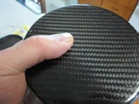
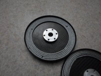
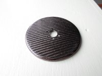
Here are a couple rotors ready for magnet bonding....
these are compresion molded rotors out of an mdf mold .08"t for back iron i have some steel cable in the same thickness as the magnets (.125"-3mm)
SAM_0063 (7).JPG
SAM_0087.JPG
SAM_0063 (11).JPG
more to follow
 
You rock Thud!! I am always stoaked to see what you build. :mrgreen:
 
Back
Top