
Hey yall I only got my D4+ 2 weeks ago and got into an accident where the display was broken and now it won't start. I'm curious to know if there is a way to bypass the display and only use the throttle? I just need it up and running soon. If not I want to get a Bluetooth controller so I can avoid this issue altogether and just build my own app to use for it. Any suggestions?
You are using an out of date browser. It may not display this or other websites correctly.
You should upgrade or use an alternative browser.
You should upgrade or use an alternative browser.
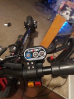
Nanrobot D4+ broken M5 Display
- Thread starter sqallFF
- Start date
Depends on how the system works.
If it's like the typical generic ebike/scooter controller, the display has an electronic switch in it that passes the battery voltage it gets back to the controller to power the controller's LVPS and turn it on, after you turn the display's power button on.
It also then commmunicates via serial between controller and display to let you change assist levels from whatever power-on level is. Often that power on level is zero, or no assist, to prevent stuck-throttle or pedalling-take-off accidents, so without the display, the system wont' provide any assist as the level can't be changed from zero.
If yours is instead like some of the scooter/motorcycle systems, the display does nothing except for displaying data, and has no assist levels or other controls routed thru it, so you'd need to find out why the system doesn't turn on (probably other wiring damage somewhere), and then the system would work with or without the display.
If yours is like some of the scooters, the throttle is part of the display, and the throttle is read by the display and coded as serial data to send to the controller, so the system can't do anything without all of these parts working.
Some systems are very proprietary and use serial data between all parts including battery to ensure it's all working and monitor status, etc., and nothing works if everything doesn't work.
Which controller, display, throttle, battery, etc does your system use?
How many pins are on the connector from the throttle/button unit? If there are only three, it's likely that it's not a standard analog throttle output and it and hte button data are sent serially, so whatever they plug into probably has to interpret the data for the controller. Other versions of this style throttle are this type of design.
If htey plug right into the controller that wont' matter, but if they go to the display first, it probably does.
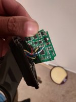
If the pic of the board and wiring is the inside of the display, then if you can post one showing the wires and the labels on the board under them (I can only see one marked DS on the white wire). That may help us find the right pair of wires to connect to turn the controller on, and then you can see if the system operates without the display or not, before going further..
")
If htey plug right into the controller that wont' matter, but if they go to the display first, it probably does.
If the pic of the board and wiring is the inside of the display, then if you can post one showing the wires and the labels on the board under them (I can only see one marked DS on the white wire). That may help us find the right pair of wires to connect to turn the controller on, and then you can see if the system operates without the display or not, before going further..
BTW, on this part, you'll probably need to reverse-engineer the BT datastream that it uses for each command and value each way (to and from the display), unless someone else has already done this for the controller you're thinking of using. If you do, please post up your results for anyone else that comes along and wishes to do the same thing.If not I want to get a Bluetooth controller so I can avoid this issue altogether and just build my own app to use for it.
Last edited:
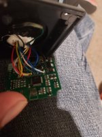
I can't really read the letters very well. With the display open like that, but plugged in and the battery connected and turned on, can you put your black lead from your multimeter (set to DCVolts) on battery negative, or any accessible ground/B- wire and then test the voltage on each of those pads with the red lead?
If the display actively switches power, there should be at least one wire that reads 0V, and one that reads battery voltage. It is highly likely that a wire right next to those is the KSI / ignition / lock wire that passes that voltage back to the controller.
Alternately, if your version of controller is one of the (silver colored) metal box types with screws on the ends, it can probably be opened up (without battery connected) to see what color the wires are that go back to near where the battery positive wires connect at the non-cable end of the controller box. (if yours is two wheel drive, there are probably two of these). If it's the black controller with two bundles of wires (one for each motor) it's probably potted and sealed and can't be opened to do this. Assuming it's like all the other controllers of this type, then one of the wires goes from battery positive up to the display, and one goes back from the display to the input of the LVPS (the part that makes the 5v and 12v/etc to run the controller). There's probably another wire from the same point that goes out to the second controller's LVPS.
Similar threads
- Replies
- 9
- Views
- 479
- Replies
- 3
- Views
- 696
- Replies
- 0
- Views
- 1,839