New temp gauge idea

Obiwan007

1 kW
Joined
Dec 16, 2012
Messages
332
Location
Northern California
So I have a small problem, my situation is that I just upgraded my wife's bike (the electric Jeepster) to a clyt HS4060 motor (thanks Ilia from ebikessf). This motor has a thermistor built in and I was planning to just hook it up the previous BBQ temp gauge I was happily using before. I had originally set it up this way with the clyt 408 motor before I knew...well...anything! This bike was built with the CA V2.3 so no temp sense or thermal roll-back. Anyway. got the new motor in and running and hooked up the temp sensor only to find that it reads radically different than it should. At ambient on a cool day it was reading 146 degrees C. I surmise that the old system used a different type of thermistor like an LM35. I'm pretty sure that the 4060 has a 10K thermistor in it to cooperate with the CA V3. I don't want to pull this motor apart to replace the sensor so I'm wondering if I can get a different, preferably inexpensive, display that will play nice with the 10K thermistor. I found this one that says it uses any "K type thermocouple":
http://www.coleparmer.com/Product/D...ermocouple_Thermometer_Fahrenheit/WU-86460-03
Does anybody know if this would work with the 10k thermistor in the crystalyte 4060? If so then I should be able to get a thermocouple plug to interface with the unit and I'll be good-to-go. Alternatively, does anybody know about an inexpensive temp gauge that will interface with the 10K thermistor?


Do you have any advice in this area? Can the HK display use either sensor? My electronic education is still in its infancy and it seems like you are stronger in this area. I don't think it is really necessary to have thermal roll-back on this bike but I am afraid to have not temp sensing at all. Any
 
a k type thermocouple do not work the same as a thermistor as it is different types of operation , the temperature reading device needs to be able to use one or the other. there are also different values of thermistor 10k is about the most common used but there are lots of available values. A LM35 is also not a thermistor its a temperature sensor and this is also different from a k thermocouple.. If you have a ohm meter you can measure the resistance of the device that you have in stalled in your wheel.. it dont need to be power to measure this will give you some idea as to the value ( if its a thermister ... )
 
If you put a resistor between the thermistor and the ca it should bring down the value of the thermistor.
 
Ya - thermocouples are a whole different ballgame. Not the right direction to head for a solution.

You need to start by finding out the exact type of device in the motor. I believe Xlyte motors use a KTY81-210.
This is a PTC device compared to the 10K NTC device that is the default for the V3. That is, the resistance increases with temperature instead of decreases. The V3 can handle this without difficulty (see the Guide).

Perhaps you might consider selling off your V2 and springing for a V3 instead - the difference in bucks might be worth the time and trouble to get something that will work with that sensor. V2's sell pretty well on ES.

Just a thought....

View attachment KTY81_SER.pdf
 
OK, I'm straightened out on the thermocouple thing (K type has nothing to do with, say 10K). Thanks for the wisdom. So Tek, you say that the crystalytes come with a PTC device instead of a NTC 10K thermistor. Now, I have learned to trust your advice but I had been thinking that crystalyte motors came with 10K thermistors because most of the motors listed on the Grin site say "10K thermistors" is what they come with. I had assumed that the stuff sold by Justin would be plug-n-play with the CA V3. String of assumptions I know. But maybe we are jus talking semantics; is the PTC device also a 10K? Anyway, I have thought of swapping out the V2.3 for a V3 but I may not need to have any heat sensing on this bike at all. I have been testing it using an IR heat gun and even with heavy hill climbing I can't get it over 40C in 19C ambient. Of course this is with the old controller settings that I have not updated yet but since this is my wife's bike she does not want the settings much higher than they are now. Also, she rides far less aggressively than me. Crea2k mentioned putting a resistor in line with the sensor to get my old BBQ meter to read right. This sounds doable if I can figure out what resistor to use. Any thoughts on how to figure that out? I'm thinking, for this bike, close will be close enough.
 
Get a variable pot and put it in the line, turn the pot until the correct temp is read, if you turn it all the way and dont get low enough you need a more resistive pot, then just use a multimeter to read the pots ohm value and you then have the value of the resistor needed. Either that or just get a few resistors and string them together until you get the right ballpark figure, then just multiply the values together. By the way the kty 81 sensor also has various versions of it that have different start and end resistance values, so if you swapped it out you can buy a few different versions of it and see which comes nearest to the correct temp. Iv got a kty 81 210 in my motor and it reads about 20 degrees higher than it should, so next time I strip the motor down il swap it for one with a different value.
 
So Ilia at ebikessf got back to me and he confirmed that the sensor in these is in fact a KTY81-210 (note to self; don't doubt Teklektik in future). Here are some parameters he sent:
Sensor = Linear Type
Units = 1.19V
T Scale = 125.0 Deg/V
Thrsh Temp = 90 Deg
Max Temp = 130 Deg
So I guess I will try the potentiometer method (I think I have one laying aroun) and see if I can dial it in for the old trusty BBQ meter.
 
O7-
Here's a little more detail that may shed some some light on the general sensor situation and the idea of adding a resistor:

There are three type of temp sensors under discussion:
  1. Thermocouples - Voltage Generating (eg K type)
    These are made of two dissimilar metals and generate a very small voltages that vary with temperature.
  2. Thermistors - Resistive (eg NTC 10K beta=3900)
    These devices develop different resistances at different temperatures.
    • NTC - Negative Temperature Coefficient
      The resistance decreases with temperature.
    • PTC - Positive temperature Coefficient
      The resistance increases with temperature.
  3. Solid State (Zener) Devices - Voltage limiting (eg LM35 LM335)
    These devices limit a voltage that is externally impressed across them in the manner of a zener diode.
Within each category there are many types. The V3 can handle many of types (2) and (3).

Here we are interested in NTC and PTC types commonly found in BBQ gauges or in ebike motors. The resistance rating (eg 10K) is the resistance at 25degC. They are typically rated at a higher temperature as well (eg 25/85 or 25/100) and the slope of the temp-to-resistance curve is related to the specified beta. In other works, different NTC 10K thermistors with different betas (different temp-to-resistance slopes) will both read 10K at 25degC but will have different resistances at 100degC. The larger the beta divergence the larger the resistance difference.

  • So - the circuit that transforms the resistance of a thermistor is very specific to whether it is NTC or PTC, the resistance at 25degC, and the specific beta of the device.
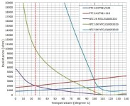
Here's some temperature to resistance curves for some NTC and PTC parts.

Sample_Ntc+PtcCurves.jpg
As you can see, the circuits to transform these very difference curves must also be very different. If fact, you can see that the 2K NTC and 2K PTC devices above both have resistances of 2000 ohms at 25degC - but the curves are such that that is the ONLY temperature where they would both yield the same temperature if put in the circuit for the other - in fact, the temperature would actually appear to be increasing/decreasing in the wrong direction.

Result - it's a pretty slim chance that just hooking a random device to a temp gauge will work properly. Similarly, just adding resistance only raises the entire curve but does not change its slope or basic NTC/PTC type. This means you may use this trick to calibrate it for one specific temperature, but it will be wrong for all other temperatures.

=====
If you have the original BBQ sensor in hand, you can take two temp/resistance measurements to help figure out the device and associated gauge. Put the sensor in a bowl of ice water (0degC) and boiling water (100degC) and measure the resistance in both cases. This will tell you if it's NTC or PTC and will allow a fair determination of the 25degC rating (eg 10K, 100K) and the beta. From this the effectiveness of using the gauge unit with your motor sensor will be apparent.

Even if it's not the proper type, from the test information it would be possible to determine a specific resistor that would make the gauge read properly at one temperature (110degC is a good point of interest where accuracy would be good). Although the normal temperature readings might be nonsense, as the temperature converged on 110degC, you would be increasingly alarmed - with good accuracy. Since you are really only interested the small range around that value anyway, the bogus readings elsewhere are immaterial....

This is an amusing example of a situation where high meter precision is not only not necessary, but the entire reading can be grossly errored except at one value - and still accomplish the job.

=====
As to the type of sensor in Xlyte motors - I said "I believe" - not stating it as fact :) . Grin Tech has 10K NTC thermistors with a beta of 3900 because when they buy motors in bulk, they specify that part. It's a purchaser specification that differs from what may otherwise by the manufacturer's common choice. So - a Grin Xlyte 4080 is almost certainly different than one from another vendor that doesn't really care about the sensor type - or is more concerned about 'standard' motor availability.
 
Wow! Now that's an explanation. Thanks Tek. I feel like I really get the idea now. It appears that for quality, configurable temp sensing the CA V3 is the best way to go here. But I think that I will likely wait a bit for that and just continue to do spot checks with the IR gun to see if the wife will get anywhere close to 110-120C. Also, since we alway ride together I can start to get an idea of what hers is doing in comparison to mine and then just keep track of it on my Giant.
 
The IR gun will only show the temps of the outside shell, and the stator in the center of the hub will be much hotter. If you ventilate the side-plates, it can let a lot of the heat out, and you might be able to get a clear shot of the stator-coils through one of the sideplate holes. Just a thought...
 
Thanks fechter. A similar doc was posted above. The other half of the equation here is to determine the device for which the O7's BBQ head unit was designed that he wanted to use with the KTY sensor.

For instance, I have a couple of the nifty BBQ temp sensors that Dr Bass recommended some time ago. Doing the ice/boiling water trick revealed the sensor to be a 130K NTC device. That head unit would never read properly for this motor sensor, but a resistor could be added so it was correct at one temp - say 100degC. In this case, since gauge expects NTC but the KTY is PTC, with the resistor the temperature would appear very high to start and would decrease towards 100deg (which would be correct). Continued gauge decrease would indicate that 100degC had been increasingly exceeded. Really not the best situation, but if those are the parts on hand, it sort of does the job....

What's too bad about this particular BBQ gauge example is that the temp alarm cannot be used with the KTY because of the NTC/PTC mismatch. With the resistor trick and KTY sensor, the indicated temp starts out reading high and then falls with increasing actual temperature. At least if the head unit expected a PTC device so the indicated temp rose with the actual temperature, the calibration temp could be set to the default temp alarm (100degC) and the alarm would work perfectly with the proper resistor....

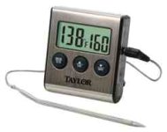
taylorDigitalThermometer.jpg
I seem to remember seeing an eBay panel meter head that was configured with coefficients for a y = mx + b linear curve so it could be used for all sorts of things. That might work in these situations by specifying the proper pull-up resistor to 5V (borrowed from the halls or throttle) and the correct m & b values to get it calibrated to the thermistor...
 
Back
Top