NMC Lithium modeling with dynamic data - megawatt hours!

Joined
Sep 11, 2015
Messages
5
Hi

I am trying to analyze terabytes worth of battery cycling and need some help. Essentially I have several megawatt hours of deployed and have been running for 1-3 years and would like to analyze the battery characteristics (Ah, equivalent resistance).

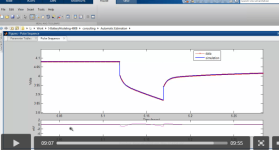
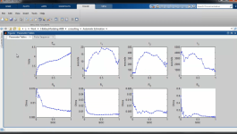
Any idea on where to start? I see matlab has a nice plugin that can estimate the parameters of a battery up to 3-RC branch circuits for high precision

http://www.mathworks.com/videos/automating-the-parameter-estimation-of-a-battery-model-95187.html

The problem is:

These batteries are in operation, and a extremely nice discharge CC pulses cannot be preformed. We have no control over the operation, we only have lots, and lots of data. Essentially it is spuratic current charging and discharging, I can post graphs later.

There are also temp sensor data every couple of cells. We have OCV data for brand new cells.

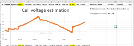
I was thinking of making an LTspice model to get it "close enough", then feed in a current profile and adjust the parameters until the simulated cell voltages matched the actual ones. It will be difficult to alter each parameter based on %SOC and temperature as matlab can do (I assume based on video). Thoughts or comments on approach?
 

Attachments

  • matlab accuracy.PNG
    matlab accuracy.PNG
    21.9 KB · Views: 785
  • matlab parameters vs SOC.PNG
    matlab parameters vs SOC.PNG
    37.6 KB · Views: 785
I'm assuming you have the SimuLink Power Systems module? Could you source a new cell that is not in use for pulse discharges?
 
Background: 95% done with a Master in Industrial Instrumentation (EE with focus on sensors (Machine vision, FPGA, signal processing etc)

I assume you have a dataset containing current, voltage and temperature with timestamp. From this, you want to quantify capacity and internal resistance without direct measurement. This can be done. I have not checked the matlab plugin and its features, but I think you're looking down the wrong path already.

First, organize the data so that you know what you do have, and what you do not.

Temperature affects internal resistance. If the battery pack go through significant temperature changes - this will mess up the internal resistance measurement. Either account for this by finding a "temperature constant" that is applied by multiplication (may be a second-order function). Or, simple way - if the average temperature stays fairly constant - you may be able to lowpass-filter several days/weeks and neglect the "temperature constant".

Capacity can be evaluated by comparing a specific "Delta V" at a fixed current. I would make a pattern of often occuring load (discharge current) and try to match the pattern with the dynamic data (Pattern matching + signal processing, search it up). If enough matches occurs, split this data out and analyze it wrt time. Make a histogram of data on current to see what patterns to try first. If one pattern is not enough - bin the different currents (using the histogram data) and run pattern matches on all bins. A pattern can be as simple as "Everytime the current is between x and y amps" - so you will be able to get some results any way you go by this.

Internal resistance affects the voltage measurement. Again, this can be accounted for by adding a "(internal resistance * current)" value to the voltage data. Alternatively, with a nice pattern and lowpass filtering - you may omit this fix. I recommend that you do not - as this will shift the voltage curve, this can result in serious error in the result.

The electrodes of the battery acts like sponges, and this also affects the measurement. Taking this into account can be done too - but I recommend a good pattern to filter this out. To make a good pattern, use conditional statements. Ex "Everytime the current is between 10 and 11 amps, and has been so for over 2 minutes". A good pointer to how long the "2 minutes" should be can be checked by what time the cell uses to stabilize voltage after removing load. Setting the "2 minutes" to about 2 tau (83 %) of full time needed to stabilize is a good tradeoff between accuracy and good pattern matching.

BTW: "We have OCV data for brand new cells." OCV is? Open Cell Voltage?

Is the data from several sites/batteries? I can think of several interesting (other than capacity and ir measurement) secondary questions that can be analyzed with the data.

Best of luck.

Edit:
Oh, nearly forgot. To measure the Internal resistance I would, once more, define a pattern. Ex. "Current change from 0A to 5A in less than 10 seconds, if current has maintained 0A for 2 minutes and voltage was between x and y volts". Then measure the voltage before and after the "current change". This will specifically target AC-IR. To measure DC-IR, the pattern needs to be longer to negate the "sponge effect". A current change from ex. 2 to 4A might perform better - since surface charge already is spent.
 
Thanks for the suggestions! I will have to look up Pattern matching + signal processing. And no, I don't have simuLink Power Systems module, I was hoping to get away with excel. It definitely cannot handle terabytes of data, but I figure I'll start with a few small samples to get the battery parameters and methods just right.

OCV I mean open circuit voltage, when the cell is not under load and has rested for a while. A good paper I've sort have been following is this:
http://www.mdpi.com/1996-1073/4/4/582/pdf

Just by using the discharge curve (OCV vs SOC) and equivalent series resistance, I have found a pretty accurate model! Averaging 0.13% error, although it does not handle transients very well. I am hoping to add one RC branch to model the transients.

The spreadsheet takes 3 parameters (starting OCV, resistance, and ampacity), and uses "solver" to optimize each value and minimize the difference between actual cell voltage and estimated cell voltage. There are 3 LONG columns of time, current, and cell voltages that it works off of.

I'm really having a hard time in excel with the RC branch. Need help!

Basically the cell voltage equation is currently: V = OCV + IR
Cell voltage equation I want: V = OCV + IR + (some undetermined equation that will take care of RC branch)

I've tried a few exponential terms like e^(-t/tau) with minimal luck. Do I have to make some sort of FIR filter?
 

Attachments

  • estimated cell voltages.PNG
    estimated cell voltages.PNG
    61.9 KB · Views: 466
Back
Top