Not simple BLDC controller It RUNS! :)

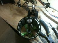
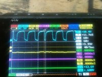
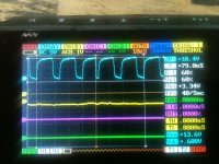
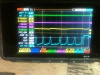
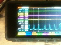
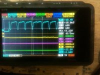
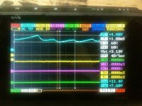
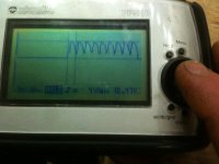
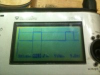
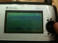
OK so I have to get a tri pod lol. I tried realy hard to get an explosion on video for you all lol. I tested for about 1 hour till I had the controller starting smoth on its own at 8v which is what I was doing all my testing at to start with. I scoped all the Low and hi side gates to source and found they were not bad in fact the HI side was clean as I think it can be. It was charging to 11.2v and was a realy clean square wave. The low side was not as clean but its hard to read because I upped the PWM to 50khz. I changed the milisec to .1 instead of 1 and that was the biggest thing to make it start with out me spining the motor. All and all great progress today realy good. I realy have a lot to learn about the code and I need to put a switch on my controller and set up the throttle so it scales. And the board doesnt want to start as soon as I turn it on. BTW I think what killed it was the ground wire that supplie the low side fet driver slipping off the aligator clip damb I forgot I wanted to solder that lol.
[youtube]wvnUW37oXLo[/youtube]
 

Attachments

  • 020.jpg
    020.jpg
    47.5 KB · Views: 3,430
  • 017.jpg
    017.jpg
    50.3 KB · Views: 3,430
  • 021.jpg
    021.jpg
    50.1 KB · Views: 3,429
Arlo1 said:
Njay said:
Way to go Arlo :D! Now to conquest the world :)
Its funny you say that. Thats what i said to my best friend last night! Just who are you mr njay if that is your real name.
Lol... What I said is a cliche, so it's coincidence. I'm in Europe Arlo :)
 
Ok.. So I rebuilt my powerstage... Yup I need to redesign it a bit for easier assembly but I think the general idea is great.
Now what I need to figure out is if a 12 tooth 14 magnet motor can have the sensors inside without knotching the teath???
I am pretty sure i have a timing issue... Here is the video and yes I will keep it at 8v untill I get it smothed out!
So does anyone know about timing the halls on a small colossus? I think its the same as a 80-100 tunigy.
[youtube]Olv1YuIqqzk[/youtube]
 

Attachments

  • 008_renamed_23080.jpg
    008_renamed_23080.jpg
    65.5 KB · Views: 3,390
Arlo1 said:
Ok.. So I rebuilt my powerstage... Yup I need to redesign it a bit for easier assembly but I think the general idea is great.
Now what I need to figure out is if a 12 tooth 14 magnet motor can have the sensors inside without knotching the teath???
I am pretty sure i have a timing issue... Here is the video and yes I will keep it at 8v untill I get it smothed out!
So does anyone know about timing the halls on a small colossus? I think its the same as a 80-100 tunigy.
[youtube]Olv1YuIqqzk[/youtube]

Same hall positions work - same as 80-100
 
Ok. So whats the 80-100 hall positions?
 
Arlo1 said:
Ok. So whats the 80-100 hall positions?


Burtie has made printable templates for placement.
 
liveforphysics said:
Arlo1 said:
Ok. So whats the 80-100 hall positions?


Burtie has made printable templates for placement.
I have the halls inside but im not sure if the timing can work inside. I thought i had it but i might have a hall reading - when it should be + hmmmm. I have to sit and draw this out....
 
Ok so I just spent the last 2 hours working on this and man something is not right! I can not for the life of me get the sensors to work with this....
I will have to do some major reading unless someone else has some input. I used my scope to set the sensors at neutral timing 60 deg mechanical or 120 and positive and negative polarity and I tired switching phase and hall wires so so many times. I also played with the code a bit but I went backwards.... My 2s lipos are dead and I need to whip something up to charge them. I tried to run it on a 12v supply but its only a 1amp and its not enough. :roll: I had one timing posistion that made the jumper wires smoke!!! I am so happy I built a cool power stage that keeps the fets cool the heat sync was at 90 degC and the fets read the same. !!!

PS thanks Luke for the Killer heat sync!
 
Arlo,
Not sure I am any help at this stage, but here is a geometric of hall position in exact nuetral position:
arlin's hall positon.jpg

Now you see that "between" any of the teeth on an 18t stator you will be + or - 5 mechanical degrees.
thats as good as it gets with this geometry & wind pattern. Also the geometry works at 120 & 60 deg interchangably as they are mechanicly identical.

I still havn't made time to play with burties timing device so no help there.
I may have just made a redundant non controbution...but if you question your hall positions this should give you a base.

:?: you speak of adjusting them into position with your scope, do you have an adjustable mounting set up I missed somewhere?

Do you have a smaller motor to play with your controller, just to get the function confirmed? before crushing it with that monster? :twisted:

if you need one let me know, I'll send you one for the project if you think it would help.
I want to see you win.
 
Thud said:
Arlo,
Not sure I am any help at this stage, but here is a geometric of hall position in exact nuetral position:


Now you see that "between" any of the teeth on an 18t stator you will be + or - 5 mechanical degrees.
thats as good as it gets with this geometry & wind pattern. Also the geometry works at 120 & 60 deg interchangably as they are mechanicly identical.

I still havn't made time to play with burties timing device so no help there.
I may have just made a redundant non controbution...but if you question your hall positions this should give you a base.

:?: you speak of adjusting them into position with your scope, do you have an adjustable mounting set up I missed somewhere?

Do you have a smaller motor to play with your controller, just to get the function confirmed? before crushing it with that monster? :twisted:

if you need one let me know, I'll send you one for the project if you think it would help.
I want to see you win.
Thanks for the offer buddy.
But this is Small colossus. 12 poll 14 mag motor. Same as a 80-100. I have to look at the code..... I think its in the code.
I have the big colossus sitting there when I prove all the functions on the small colossus!
I can tell from the playing I have done these IRFP4668 fets are tough!! I am very happy with my layout for my powerstage it soaks the heat away from the fets fast!

I used a 4ch el-cheepo oscilloscope to line the hall up to the sign wave produced by the motor when I spin it with my finger. I will go read the Hall sensing function and see if I can understand it... Small steps but always moving forward :) Like a wise man once said "its like eating an elephant just have to eat a chunk at a time ;)"
 
The controller IC you got coming in the mail has simple to use hall position / coil position measurement
functions with table out (which you can copy/paste in a spreadsheet program to make a graph)...

Smoke coming of wires :mrgreen: this reminds me of the time I built a 500 Watt shortwave
transmitter with vacuum tubes (drew 1A from a 1200V supply). Things go so hot there
a (naked) resistor I had hanging in mid-air unsoldered itself and fell off, drawing a very long
arc (cool :D ) Drove those tubes till they went tomato-red and de-gassed the metal in them,
made them light up all blue. Funny was also that when I pressed the morse-key the light in the
room dimmed and it was a 50/50 change that on plugging it in the fuses in the house's main
switch box blew :mrgreen: Things got scary when a fuse holder (220V fuse in 1200V line)
exploded like a fire-cracker spewing bits of plastic all over the room (luckely not in my eyes).
I think the few blew, drew an arc which super-heated the air which exploded the fuse holder...
 
Lebowski said:
The controller IC you got coming in the mail has simple to use hall position / coil position measurement
functions with table out (which you can copy/paste in a spreadsheet program to make a graph)...

Smoke coming of wires :mrgreen: this reminds me of the time I built a 500 Watt shortwave
transmitter with vacuum tubes (drew 1A from a 1200V supply). Things go so hot there
a (naked) resistor I had hanging in mid-air unsoldered itself and fell off, drawing a very long
arc (cool :D ) Drove those tubes till they went tomato-red and de-gassed the metal in them,
made them light up all blue. Funny was also that when I pressed the morse-key the light in the
room dimmed and it was a 50/50 change that on plugging it in the fuses in the house's main
switch box blew :mrgreen: Things got scary when a fuse holder (220V fuse in 1200V line)
exploded like a fire-cracker spewing bits of plastic all over the room (luckely not in my eyes).
I think the few blew, drew an arc which super-heated the air which exploded the fuse holder...
Thanks lebowski. I am excited to try that chip from you I will wire up the proto board I have for it. But like I was telling Todd though email I have less time invested into this controller so far then I do modding and destroying 18/24/36 fet controllers only to want to cry when I turn the throttle ~5% and here a small pop and the dam thing is dead all because it was never designed to run a motor like colossus. For those of you who haven't build or modded a controller of any kind I typically put 8-12 hours into a 18 or 24 or 36 fet controller and 6-8 hours into a 12 fet controller. When you buy one from lyen with almost the same amount of love I put into mine you are getting a amazing deal! This controller once we get a pcb made for the brain and the power-stage will take ~ 3-6hr for a 6-12 fet and 6-8hr for a 24-36 fet hours to build and I'm guessing not to long to program. I should also have my big dyno done for some inertia loads (hope to add burties load cell as well) and some very repeatable results with in a month or two so just in time for some awesome fet destruction!!!
 
Lebowski said:
The controller IC you got coming in the mail has simple to use hall position / coil position measurement
functions with table out (which you can copy/paste in a spreadsheet program to make a graph)...

Smoke coming of wires :mrgreen: this reminds me of the time I built a 500 Watt shortwave
transmitter with vacuum tubes (drew 1A from a 1200V supply). Things go so hot there
a (naked) resistor I had hanging in mid-air unsoldered itself and fell off, drawing a very long
arc (cool :D ) Drove those tubes till they went tomato-red and de-gassed the metal in them,
made them light up all blue. Funny was also that when I pressed the morse-key the light in the
room dimmed and it was a 50/50 change that on plugging it in the fuses in the house's main
switch box blew :mrgreen: Things got scary when a fuse holder (220V fuse in 1200V line)
exploded like a fire-cracker spewing bits of plastic all over the room (luckely not in my eyes).
I think the few blew, drew an arc which super-heated the air which exploded the fuse holder...

Wow! Some people have all the fun. Sounds like you found the magic plasma.
 
Ok So I just made some progress. I found I had my PW1 H and low backwards and my PWM 2 H and low backwards... Now I don't have a clean signal on pwm 1 but the PWM 2 and 3 are perfect. I Have it running on the working signals really smooth. I will try to work this out tonight. Then its on to understanding more about the programing. Even though I have a Couple pic Chips coming from Lebowski I will keep working on this and keep it open source.
 
OK so for now on I will edit my frist post in this thread to include the current code I am using.
It feels so good to have this running properly.

Here is where I am at
Code:
#define   __dsPIC30F4011__
#include "p30F4011.h"
//Configuration bits
_FOSC(CSW_FSCM_OFF & FRC_PLL4);
_FWDT(WDT_OFF);
_FBORPOR (PBOR_OFF & PWRT_16 & MCLR_EN);
_FGS(CODE_PROT_OFF);
//-----------------------------------------------------------------------------
//Program Specific Constants
//Fcy = cycle clock = Fosc/4 = (XTAL * PLLmultiplier)/(4*PostScaler)
#define FCY 5000000        // 5 MHz Xtal*PLLof4/(4*Postscalerof1)
#define MILLISEC       FCY/10000       // 1 mSec delay constant
#define FPWM 16000       // 50 kHz, so that no audible noise is present. (from sensorless code)
#define Ksp 1200
#define Ksi 10
#define RPMConstant 60* (FCY/256)
/* PWMCON1 */
#define _PEN1L PWMCON1bits.PEN1L
#define _PEN2L PWMCON1bits.PEN2L
#define _PEN3L PWMCON1bits.PEN3L
#define _PEN1H PWMCON1bits.PEN1H
#define _PEN2H PWMCON1bits.PEN2H
#define _PEN3H PWMCON1bits.PEN3H
#define _PMOD1 PWMCON1bits.PMOD1
#define _PMOD2 PWMCON1bits.PMOD2
#define _PMOD3 PWMCON1bits.PMOD3
#define _PTMOD PTCONbits.PTMOD
#define _PTCKPS PTCONbits.PTCKPS
#define _PTOPS PTCONbits.PTOPS
#define _DTBPS DTCON1bits.DTBPS
#define _DTAPS DTCON1bits.DTAPS
void InitTMR3(void);
void InitADC10(void);
void AverageADC(void);
void DelayNmSec(unsigned int N);
void InitMCPWM(void);
void CalculateDC(void);
void GetSpeed(void);
struct {
unsigned RunMotor : 1;
unsigned Minus : 1;
unsigned unused : 14;
} Flags;
unsigned int HallValue;
int Speed;
unsigned int Timer3;
unsigned char Count;
unsigned char SpeedCount;
int DesiredSpeed;
int ActualSpeed;
int SpeedError;
int DutyCycle;
int SpeedIntegral;
/*************************************************************
Low side driver table is as below. In this StateLoTable,
the Low side driver is PWM while the high side driver is
either on or off. This table is used in this exercise
*************************************************************/
unsigned int StateLoTable[] = {0x0000, 0x1002, 0x0420, 0x0402,
0x0108, 0x1008, 0x0120, 0x0000};
/****************************************************************
Interrupt vector for Change Notification CN5, 6 and 7 is as below.
When a Hall sensor changes states, an interrupt will be caused which
will vector to the routine below.
The user has to then read the PORTB, mask bits 3, 4 and 5,
shift and adjust the value to read as 1, 2 ... 6. This
value is then used as an offset in the lookup table StateLoTable
to determine the value loaded in the OCDCON register
*****************************************************************/
void _ISR _CNInterrupt(void)
{
IFS0bits.CNIF = 0; // clear flag
HallValue = PORTB & 0x0038; // mask RB3,4 & 5
HallValue = HallValue >> 3; // shift right 3 times
OVDCON = StateLoTable[HallValue];// Load the overide control register
}
/*********************************************************************
The ADC interrupt loads the DesiredSpeed variable with the demand pot
value. This is then used to determing the Speed error. When the motor
is not running, the PDC values use the direct Demand value from the pot.
*********************************************************************/
void _ISR _ADCInterrupt(void)
{
IFS0bits.ADIF = 0;
DesiredSpeed = ADCBUF0;
if (!Flags.RunMotor)
{
PDC1 = ADCBUF0; // get value ...
PDC2 = PDC1; // and load all three PWMs ...
PDC3 = PDC1; // duty cycles
}
}
/************************************************************************
The main routine controls the initialization, and the keypress to start
and stop the motor.
************************************************************************/
int main(void)
{
LATE = 0x0000;
TRISE = 0xFFC0; // PWMs are outputs
CNEN1 = 0x00E0; // CN5,6 and 7 enabled
CNPU1 = 0x00E0; // enable internal pullups
IFS0bits.CNIF = 0; // clear CNIF
IEC0bits.CNIE = 1; // enable CN interrupt
SpeedError = 0;
SpeedIntegral = 0;
InitTMR3();
InitMCPWM();
InitADC10();
while(1)
{
DelayNmSec(10);
// read hall position sensors on PORTB
HallValue = PORTB & 0x0038; // mask RB3,4 & 5
HallValue = HallValue >> 3; // shift right to get value 1, 2 ... 6
OVDCON = StateLoTable[HallValue];// Load the overide control register
PWMCON1 = 0x0777; // enable PWM outputs
Flags.RunMotor = 1; // set flag
T3CON = 0x8030; // start TMR3
while (Flags.RunMotor) // while motor is running
   {
if (HallValue == 1) //IF in sector 1
{
HallValue = 0xFF; // force a new value as a sector
if (++Count == 5) // do this for 5 electrical revolutions or 1
// mechanical revolution for a 10 pole motor
{
Timer3 = TMR3;// read latest tmr3 value
TMR3 = 0;
Count = 0;
GetSpeed();// determine spped
}
}
Flags.RunMotor = 0;// reset run flag
DelayNmSec(10);
}
} // end of while (1)
}
/*******************************************************************
Below is the code required to setup the ADC registers for :
1. 1 channel conversion (in this case RB2/AN2)
2. PWM trigger starts conversion
3. Pot is connected to CH0 and RB2
4. Manual Stop Sampling and start converting
5. Manual check of Conversion complete
*********************************************************************/
void InitADC10(void)
{
ADPCFG = 0xFFFB; // all PORTB = Digital;RB0 to RB2 = analog
ADCON1 = 0x0064; // PWM starts conversion
ADCON2 = 0x0000; // sample CH0 channel
ADCHS = 0x0002; // Connect RB2/AN2 as CH0 = pot.
ADCON3 = 0x0080; // Tad = internal RC (4uS)
IFS0bits.ADIF = 0; // clear flag
IEC0bits.ADIE = 1; // enable interrupt
ADCON1bits.ADON = 1; // turn ADC ON
}
/********************************************************************
InitMCPWM, intializes the PWM as follows:
1. FPWM = 16000 hz
2. Independant PWMs
3. Control outputs using OVDCON
4. Set Duty Cycle using PI algorithm and Speed Error
5. Set ADC to be triggered by PWM special trigger
*********************************************************************/
 void InitMCPWM(void)
   {
   PTPER = FCY/FPWM -1;
   _PTOPS = 0x0;   // Postscale (1:1)
   _PTCKPS = 0x0;  // Prescale Tcy (1:1)
   _PTMOD = 0b11;   // PWM continious up/down with dual up dates
   _PMOD3 = 0x0;  // PWM pair is complementary
   _PMOD2 = 0x0;
   _PMOD1 = 0x0;
   _PEN1H = 0x1;   // enable for output
   _PEN2H = 0x1;
   _PEN3H = 0x1;
   _PEN1L = 0x1;
   _PEN2L = 0x1;
   _PEN3L = 0x1; 
   _DTBPS = 0x0;     // Dead time unit B  1 Tcy
   _DTAPS = 0x0;     // Dead time unit A 1 Tcy
 #define  FLTACONbits.FAEN3 = 0x0;   // PWM pins not controlled by fault A input.
 #define  FLTACONbits.FAEN2 = 0x0;
 #define  FLTACONbits.FAEN1 = 0x0;
 #define  FLTBCONbits.FAEN3 = 0x0;   // PWM pins not controlled by fault B input
 #define FLTBCONbits.FAEN1 = 0x0;
 #define FLTBCONbits.FAEN2 = 0x0;
 #define  OVDCONbits.POVD1L = 0x1;   // PWM pins controlled by PWM generator
 #define  OVDCONbits.POVD2L = 0x1;
 #define  OVDCONbits.POVD3L = 0x1;
   PDC1 = 50;                 // init PWM to 50
   PDC2 = 50;
   PDC3 = 50;
   PTCON = 0x8000; // start PWM
   }

/************************************************************************
Tmr3 is used to determine the speed so it is set to count using Tcy/256
*************************************************************************/
void InitTMR3(void)
{
T3CON = 0x0030; // internal Tcy/256 clock
TMR3 = 0;
PR3 = 0x8000;
}
/************************************************************************
GetSpeed, determins the exact speed of the motor by using the value in
TMR3 for every mechanical cycle.
*************************************************************************/
void GetSpeed(void)
{
if (Timer3 > 23000) // if TMR3 is large ignore reading
return;
if (Timer3 > 0)
Speed = RPMConstant/(long)Timer3;// get speed in RPM
ActualSpeed += Speed;
ActualSpeed = ActualSpeed >> 1;
if (++SpeedCount == 1)
{SpeedCount = 0;CalculateDC();}
}
/*****************************************************************************
CalculateDC, uses the PI algorithm to calculate the new DutyCycle value which
will get loaded into the PDCx registers.
****************************************************************************/
void CalculateDC(void)
{
DesiredSpeed = DesiredSpeed*3;
Flags.Minus = 0;
if (ActualSpeed > DesiredSpeed)
SpeedError = ActualSpeed - DesiredSpeed;
else
{
SpeedError = DesiredSpeed - ActualSpeed;
Flags.Minus = 1;
}
SpeedIntegral += SpeedError;
if (SpeedIntegral > 9000)
SpeedIntegral = 0;
DutyCycle = (((long)Ksp*(long)SpeedError + (long)Ksi*(long)SpeedIntegral) >> 12);
DesiredSpeed = DesiredSpeed/3;
if (Flags.Minus)
DutyCycle = DesiredSpeed + DutyCycle;
else DutyCycle = DesiredSpeed - DutyCycle;
if (DutyCycle < 100)
DutyCycle = 100;
if (DutyCycle > 1250)
{DutyCycle = 1250;SpeedIntegral = 0;}
PDC1 = DutyCycle;
PDC2 = PDC1;
PDC3 = PDC1;
}
//---------------------------------------------------------------------
// This is a generic 1ms delay routine to give a 1mS to 65.5 Seconds delay
// For N = 1 the delay is 1 mS, for N = 65535 the delay is 65,535 mS.
// Note that FCY is used in the computation. Please make the necessary
// Changes(PLLx4 or PLLx8 etc) to compute the right FCY as in the define
// statement above.
void DelayNmSec(unsigned int N)
{
unsigned int j;
while(N--)
for(j=0;j < MILLISEC;j++);
}
and here is a video of some testing now that I have it all working properly The harmonics when I rev it are because the magnet can is just slid on not locked.
[youtube]n4s1yA3aYgI[/youtube]
 
OK so here is a few scope pics trying 40 khz pwm and 50 khz pwm and I need to mention the video had the PWM at 16 khz which explains some other things to my self. At ~50 khz the throttle will make the rpm go down because I am using all the power of the 1 amp power supply running the motor. This stuff is so so cool. I already want to write code to make it switch to lower pwm at higher rpm lol.

The difference in the pwm on time in the 50 khz is from the controller updating the on time to maintiain rpm. I will go get a non dead battery and continue.
 

Attachments

  • 003.jpg
    003.jpg
    87.2 KB · Views: 3,468
  • 005.jpg
    005.jpg
    88.3 KB · Views: 3,468
  • 007.jpg
    007.jpg
    82.6 KB · Views: 3,468
  • 009.jpg
    009.jpg
    85.4 KB · Views: 3,468
  • 011.jpg
    011.jpg
    81.3 KB · Views: 3,468
  • 012.jpg
    012.jpg
    86 KB · Views: 3,468
Look what saulty9 found from a link I posted for a dspic30f protoboard. http://www.futurlec.com/Mini_Opto_Isolator.shtml I am just heading out for work but I am not sure the specs. I will likely order a couple of these soon.
 
PC817 is slow when used at your speed, check the data sheet. Use logic signal isolators, they are faster.

There are also gate drivers with built in opto isolation, like FOD3120 and similar.
 
bearing said:
PC817 is slow when used at your speed, check the data sheet. Use logic signal isolators, they are faster.

There are also gate drivers with built in opto isolation, like FOD3120 and similar.
Cool thanks. I will look into it. I think what I have built is pretty good I am just not sure what all I need to do to protect the main dspic chip. I know I am going to blow some fets up loading them down when I do some destructive testing. So I want to protect the brain!
 
What do you guys think about this as a powerstage for higher power stuff....? http://www.pwrx.com/pwrx/docs/bp6a_application_note.pdf
 
Digikey wants a lot of money. But Ive been told there is a sorce from china that we can get them for ~400. The biggest advantage with these is they have gate drive built into them so it makes a cleaner quicker build!
 
Hi Arlo, sorry I'm late.

I just sent off some enquiries to see what the 450amp and 600amp version of those IGBT IMPs cost. I'll let you know what I find out.

I did enquire a while back at digikey and in addition to cost, the lead time was measured in months :roll:

Its still not a sure thing that I'll be able to build this for a class project, but it would still make for a nice clean build.
 
Hey david better late then never. Its all good there is no one "right" way just good ways and bad ways to do it!
 
Got a reply from one of my inquiries. The PM450CLA060 (450amp) is $412 and the PM600CLA060 (600 amp) is $560. Shipping was estimated at $33.
 
Back
Top