Not simple BLDC controller It RUNS! :)

This it my scope at the fet gates. It will give a pulse of .3xx ms So I think everything is ok but I might need to up the power supply voltage to ~15 instead of 12????
The gates are getting around 10v.....
[youtube]EC9zzXJe2Dw[/youtube]
 
Arlo1 said:
Whats the minumum voltage to turn a 4115 mosfet on?
The Vgate threshold is around 3 volts and the Miller plateau is around 7 volts. That means it should start to come on a little over 3 and should be full on around 7 and a touch.
 
bigmoose said:
Arlo1 said:
Whats the minumum voltage to turn a 4115 mosfet on?
The Vgate threshold is around 3 volts and the Miller plateau is around 7 volts. That means it should start to come on a little over 3 and should be full on around 7 and a touch.
Ok thanks Dave. I just found the chart my self and its good to verify I understand it properly. I must have something wrong with the fets them selfs.
 
Found I had a mosfet in backwards lol I thought I fix three of them but I must have put one in bacwards in a hurry. I fixed it and now I have noise that comes to the motor and it gets louder when I turn the throttle.... I Scoped it again and its back to 8.6 uS max on time..... I think I will look at the crystal tomorow and maybe swap it out. Getting there...
 
So I whipped up another controller with a dspic30f4011 because they showed up in the mail today and they are PDIP lol. But the funny thing is I am having the same problems as before. I am not sure but Its time to realy dig into the code. Because its weird that I got it to scope whith what looked proper once and only once.
 

Attachments

  • 022_renamed_2555.jpg
    022_renamed_2555.jpg
    61.1 KB · Views: 1,837
  • 021_renamed_15444.jpg
    021_renamed_15444.jpg
    83.3 KB · Views: 1,837
  • 023_renamed_15820.jpg
    023_renamed_15820.jpg
    72 KB · Views: 1,837
I started my own power stage build thread and in the spirit of keeping the brain and the power stage seprate its posted here http://www.endless-sphere.com/forums/viewtopic.php?f=30&t=35387&p=516004#p516004
 
Ok so here is a scope shot of one side of the 5mhz crystal to ground.... The other side to ground is smoth and looks like its low. I used 22pf caps from each side the crystal to ground. Should I take the side with this shot and add a resistor???
 

Attachments

  • 001 (800 x 600).jpg
    001 (800 x 600).jpg
    72.2 KB · Views: 1,753
Arlo, do you have these registers set properly for an XT crystal (assuming you are using 5MHz)? See below:
 
I tried a bunch of settings I found this
http://ww1.microchip.com/downloads/en/DeviceDoc/70268A.pdf


Code:
#define   __dsPIC30F4011__
#include "p30F4011.h"
//Configuration bits
_FOSC(CSW_FSCM_OFF & XT_PLL4);
_FWDT(WDT_OFF);
_FBORPOR (PBOR_OFF & PWRT_16 & MCLR_EN);
_FGS(CODE_PROT_OFF);
//-----------------------------------------------------------------------------
//Program Specific Constants
//Fcy = cycle clock = Fosc/4 = (XTAL * PLLmultiplier)/(4*PostScaler)
#define FCY             5000000        // 5 MHz Xtal*PLLof4/(4*Postscalerof1)
#define MILLISEC       FCY/10000       // 1 mSec delay constant
#define FPWM 20000       // 20 kHz, so that no audible noise is present. (from sensorless code)
#define Ksp 1200
#define Ksi 10
#define RPMConstant 60* (FCY/256)
void InitTMR3(void);
void InitADC10(void);
void AverageADC(void);
void DelayNmSec(unsigned int N);
void InitMCPWM(void);
void CalculateDC(void);
void GetSpeed(void);
struct {
unsigned RunMotor : 1;
unsigned Minus : 1;
unsigned unused : 14;
} Flags;
unsigned int HallValue;
int Speed;
unsigned int Timer3;
unsigned char Count;
unsigned char SpeedCount;
int DesiredSpeed;
int ActualSpeed;
int SpeedError;
int DutyCycle;
int SpeedIntegral;
/*************************************************************
Low side driver table is as below. In this StateLoTable,
the Low side driver is PWM while the high side driver is
either on or off. This table is used in this exercise
*************************************************************/
unsigned int StateLoTable[] = {0x0000, 0x1002, 0x0420, 0x0402,
0x0108, 0x1008, 0x0120, 0x0000};
/****************************************************************
Interrupt vector for Change Notification CN5, 6 and 7 is as below.
When a Hall sensor changes states, an interrupt will be caused which
will vector to the routine below.
The user has to then read the PORTB, mask bits 3, 4 and 5,
shift and adjust the value to read as 1, 2 ... 6. This
value is then used as an offset in the lookup table StateLoTable
to determine the value loaded in the OCDCON register
*****************************************************************/
void _ISR _CNInterrupt(void)
{
IFS0bits.CNIF = 0; // clear flag
HallValue = PORTB & 0x0038; // mask RB3,4 & 5
HallValue = HallValue >> 3; // shift right 3 times
OVDCON = StateLoTable[HallValue];// Load the overide control register
}
/*********************************************************************
The ADC interrupt loads the DesiredSpeed variable with the demand pot
value. This is then used to determing the Speed error. When the motor
is not running, the PDC values use the direct Demand value from the pot.
*********************************************************************/
void _ISR _ADCInterrupt(void)
{
IFS0bits.ADIF = 0;
DesiredSpeed = ADCBUF0;
if (!Flags.RunMotor)
{
PDC1 = ADCBUF0; // get value ...
PDC2 = PDC1; // and load all three PWMs ...
PDC3 = PDC1; // duty cycles
}
}
/************************************************************************
The main routine controls the initialization, and the keypress to start
and stop the motor.
************************************************************************/
int main(void)
{
LATE = 0x0000;
TRISE = 0xFFC0; // PWMs are outputs
CNEN1 = 0x00E0; // CN5,6 and 7 enabled
CNPU1 = 0x00E0; // enable internal pullups
IFS0bits.CNIF = 0; // clear CNIF
IEC0bits.CNIE = 1; // enable CN interrupt
SpeedError = 0;
SpeedIntegral = 0;
InitTMR3();
InitMCPWM();
InitADC10();
while(1)
{
DelayNmSec(10);
// read hall position sensors on PORTB
HallValue = PORTB & 0x0038; // mask RB3,4 & 5
HallValue = HallValue >> 3; // shift right to get value 1, 2 ... 6
OVDCON = StateLoTable[HallValue];// Load the overide control register
PWMCON1 = 0x0777; // enable PWM outputs
Flags.RunMotor = 1; // set flag
T3CON = 0x8030; // start TMR3
while (Flags.RunMotor) // while motor is running
   {
if (HallValue == 1) //IF in sector 1
{
HallValue = 0xFF; // force a new value as a sector
if (++Count == 5) // do this for 5 electrical revolutions or 1
// mechanical revolution for a 10 pole motor
{
Timer3 = TMR3;// read latest tmr3 value
TMR3 = 0;
Count = 0;
GetSpeed();// determine spped
}
}
PWMCON1 = 0x0700;// disable PWM outputs
OVDCON = 0x0000; // overide PWM low.
Flags.RunMotor = 0;// reset run flag
DelayNmSec(10);
}
} // end of while (1)
}
/*******************************************************************
Below is the code required to setup the ADC registers for :
1. 1 channel conversion (in this case RB2/AN2)
2. PWM trigger starts conversion
3. Pot is connected to CH0 and RB2
4. Manual Stop Sampling and start converting
5. Manual check of Conversion complete
*********************************************************************/
void InitADC10(void)
{
ADPCFG = 0xFFF8; // all PORTB = Digital;RB0 to RB2 = analog
ADCON1 = 0x0064; // PWM starts conversion
ADCON2 = 0x0000; // sample CH0 channel
ADCHS = 0x0002; // Connect RB2/AN2 as CH0 = pot.
ADCON3 = 0x0080; // Tad = internal RC (4uS)
IFS0bits.ADIF = 0; // clear flag
IEC0bits.ADIE = 1; // enable interrupt
ADCON1bits.ADON = 1; // turn ADC ON
}
/********************************************************************
InitMCPWM, intializes the PWM as follows:
1. FPWM = 16000 hz
2. Independant PWMs
3. Control outputs using OVDCON
4. Set Duty Cycle using PI algorithm and Speed Error
5. Set ADC to be triggered by PWM special trigger
*********************************************************************/
void InitMCPWM(void)
{
PTPER = FCY/FPWM - 1;
PWMCON1 = 0x0700; // disable PWMs
OVDCON = 0x0000; // allow control using OVD
PDC1 = 100; // init PWM 1, 2 and 3 to 100
PDC2 = 100;
PDC3 = 100;
SEVTCMP = PTPER; // special trigger is 16 period values
PWMCON2 = 0x0F00; // 16 postscale values
PTCON = 0x8000; // start PWM
}
/************************************************************************
Tmr3 is used to determine the speed so it is set to count using Tcy/256
*************************************************************************/
void InitTMR3(void)
{
T3CON = 0x0030; // internal Tcy/256 clock
TMR3 = 0;
PR3 = 0x8000;
}
/************************************************************************
GetSpeed, determins the exact speed of the motor by using the value in
TMR3 for every mechanical cycle.
*************************************************************************/
void GetSpeed(void)
{
if (Timer3 > 23000) // if TMR3 is large ignore reading
return;
if (Timer3 > 0)
Speed = RPMConstant/(long)Timer3;// get speed in RPM
ActualSpeed += Speed;
ActualSpeed = ActualSpeed >> 1;
if (++SpeedCount == 1)
{SpeedCount = 0;CalculateDC();}
}
/*****************************************************************************
CalculateDC, uses the PI algorithm to calculate the new DutyCycle value which
will get loaded into the PDCx registers.
****************************************************************************/
void CalculateDC(void)
{
DesiredSpeed = DesiredSpeed*3;
Flags.Minus = 0;
if (ActualSpeed > DesiredSpeed)
SpeedError = ActualSpeed - DesiredSpeed;
else
{
SpeedError = DesiredSpeed - ActualSpeed;
Flags.Minus = 1;
}
SpeedIntegral += SpeedError;
if (SpeedIntegral > 9000)
SpeedIntegral = 0;
DutyCycle = (((long)Ksp*(long)SpeedError + (long)Ksi*(long)SpeedIntegral) >> 12);
DesiredSpeed = DesiredSpeed/3;
if (Flags.Minus)
DutyCycle = DesiredSpeed + DutyCycle;
else DutyCycle = DesiredSpeed - DutyCycle;
if (DutyCycle < 100)
DutyCycle = 100;
if (DutyCycle > 1250)
{DutyCycle = 1250;SpeedIntegral = 0;}
PDC1 = DutyCycle;
PDC2 = PDC1;
PDC3 = PDC1;
}
//---------------------------------------------------------------------
// This is a generic 1ms delay routine to give a 1mS to 65.5 Seconds delay
// For N = 1 the delay is 1 mS, for N = 65535 the delay is 65,535 mS.
// Note that FCY is used in the computation. Please make the necessary
// Changes(PLLx4 or PLLx8 etc) to compute the right FCY as in the define
// statement above.
void DelayNmSec(unsigned int N)
{
unsigned int j;
while(N--)
for(j=0;j < MILLISEC;j++);
}
This is the last try on the code
 

Attachments

  • oscilator (800 x 476).jpg
    oscilator (800 x 476).jpg
    31.5 KB · Views: 1,748
I just tried
Code:
_FOSC(CSW_FSCM_OFF & FRC_PLL4);
To use the internal oscilator but Im not sure if I have it right. I will have to do some more reading tonight.
 
these are my settings

Code:
    config __FOSC, FRC_PLL16 & PRI & CSW_FSCM_OFF
    config __FWDT, WDT_OFF

with these you don't need an external oscillator and they will make the 30F4011-30 run
at it maximum speed. The WDT_OFF is a handy one to include else the chip will
'misteriously' reset every 20 seconds or so.
 
Lebowski said:
these are my settings

Code:
    config __FOSC, FRC_PLL16 & PRI & CSW_FSCM_OFF
    config __FWDT, WDT_OFF

with these you don't need an external oscillator and they will make the 30F4011-30 run
at it maximum speed. The WDT_OFF is a handy one to include else the chip will
'misteriously' reset every 20 seconds or so.
Thanks lebowski IM all the way back to the pwm at the fets but I think the halls in my turnigy 7kw might be in the wrong tooth.

On another note my C30 compiler only has 14 days left????? What the hell I though it was a free version so no I have to pay????????
 
Arlo1 said:
Thanks lebowski IM all the way back to the pwm at the fets but I think the halls in my turnigy 7kw might be in the wrong tooth.

On another note my C30 compiler only has 14 days left????? What the hell I though it was a free version so no I have to pay????????

Just wait for my chip :D 
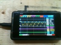
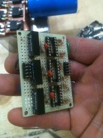
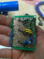
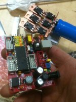
it'll tell you how all the halls are related to each other and to the back-emf

I don't know about C compiler, I do everything in assembly which is not complaining after about 3 months of
using it...
 
Right now my problem is in my powerstage I think the gate caps are to small I have to figure out how to size them, Im REALY excited to try your chip lebowski as well But I also want to learn how to do all this its so rewarding after a long hard haul!
 
Whiped up another power stage and a driver board this weekend. Man this stuff can be time consuming...
And guess what showed up today!!!
 

Attachments

  • 028.jpg
    028.jpg
    66.4 KB · Views: 1,902
  • 029.jpg
    029.jpg
    67.8 KB · Views: 1,902
  • 021.jpg
    021.jpg
    71.4 KB · Views: 1,902
  • 023_renamed_32730.jpg
    023_renamed_32730.jpg
    71.1 KB · Views: 1,902
  • 033.jpg
    033.jpg
    73.6 KB · Views: 1,902
Ok so Im going though the Motor control PWM section of the dspic30f family manual
And I don't quite know how to put the actual code together. For instance if I want to make a line saying
//PWM time base operates in a continuous up/down mode with interrupts for double PWM updates

Do I Write it
Code:
 PTMOD = 11;   //       //PWM time base operates in a continuous up/down mode with interrupts for double PWM updates
?
 

Attachments

  • Capture  Family manual.JPG
    Capture Family manual.JPG
    48.3 KB · Views: 1,858
isn't it something like this in C ?

Code:
PTCONbits.PTMOD = ..

man C is hard

maybe its easier to do like I do, determine all the settings you want for a
certain register (PTCON in this case) and then assign all of them in one go with
one instruction

Code:
PTCON = 0x....

Then later if you want to flip a single bit you can go back using PTCONbits.XXX = X
 
in C,
0b prefix indicates binary representation
0x prefix indicates hexadecimal representation

The definitions from the data sheet (shown above) are in binary

So you might want to try

Code:
PTCONbits.PTMOD = 0b11; //  this one is binary format

alternatively, you could try

Code:
PTCONbits.PTMOD = 0x3;  // this is in hexadecimal format


Burtie
 
I am quite religious about writing my code as understandable as possible over writing coments.

I (and I belive many other like to do something like this:

#define PTMOD_PWM_MODE_INT 0b11
#define PTMOD_PWM_MODE_CONT 0b10
#define PTMOD_PWM_MODE_SINGLE 0b01
#define PTMOD_PWM_MODE_FREE 0b00

#define PTCKPS_PRESCALE_64 0b11
#define PTCKPS_PRESCALE_16 0b10
#define PTCKPS_PRESCALE_4 0b01
#define PTCKPS_PRESCALE_1 0b00

The point of the is that you can then just write like:

*PTCKPS_reg = PTMOD_PWM_MODE_INT | anoter_bit | another_bit;

And you can see directly in the code what is going on.

It is a bit of work to set up all the defines, but most decent chip vendors supplies this for you, you just have to find them.

Writing readable code always pays of, in real life code is written once, rewritten 10 times and read 10000 times.
 
I have noticed something a little strange going on in this thread. Currently, I am the only one here except for 8 guests. At one point when I checked this morning (PSTime) there were 30 guests and me. There are many very curious "guests" out there following this thread. A whole lot more than normal :!: :shock: :mrgreen:
 
Its because there are many newbs like me who are cluesless with code and other parts of this so they want to learn and i want this all to be public knoladge! And yup you guys all got me Very confused :)
 
Ok So I just found the programmers reference manual http://ocw.um.es/ingenierias/sistemas-embebidos/practicas-1/ssee-da-lab-03.pdf
 
Damb I whipped everything together with my new ribbon cable and nothing scoped it to find no pwm on the hi side.....
:Edit.... I have some digging to do... I scoped the dspic30f it self and how no outputs... I have some tests to run and some code so go over. for one I found in the dspic30f family manual that the ADC10 function should have this line
Code:
ADPCFG = 0xFFFB; // all PORTB = Digital; RB2 = analog
WHere I had
Code:
ADPCFG = 0xFFF8; // all PORTB = Digital; RB2 = analog

Its going to be a long road... But I will get there.
 
Back
Top