
You are using an out of date browser. It may not display this or other websites correctly.
You should upgrade or use an alternative browser.
You should upgrade or use an alternative browser.
Not simple BLDC controller It RUNS! :)
- Thread starter Arlo1
- Start date
Ok so this builds. But im still learning. IM not sure of it for I have not put anything in the while 1 loop.
Yes I stole code again.... I also understand some of it lol. I am reading the last link I find this one to be the best one!
I really feel good about this and I can't wait to REALY get flying with this... I will be working on this for the rest of the night then a bit over the next few days! Till boxing day when I hope to really start digging in with it! Thanks for being patient guys! I have big things planned!!!
Code:
#define  __p30F3010__
#include  "p30F3010.h"                 // put compiler dsPIC.h file in root
#include  "adc10.h"
#include  "delay.h"
//-----------------------------------------------------------------------------
//Configuration bits
_FOSC(CSW_FSCM_OFF & XT_PLL4);
_FWDT(WDT_OFF);
_FBORPOR (PBOR_OFF & PWRT_16 & MCLR_EN);
_FGS(CODE_PROT_OFF);
//-----------------------------------------------------------------------------
//Program Specific Constants
//Fcy = cycle clock = Fosc/4 = (XTAL * PLLmultiplier)/(4*PostScaler)
#define FCY             5000000        // 5 MHz Xtal*PLLof4/(4*Postscalerof1)
#define MILLISEC       FCY/10000       // 1 mSec delay constant
#define FPWM 20000		 // 20 kHz, so that no audible noise is present. (from sensorless code)

// Put global variables here
unsigned int ADCValue;
unsigned int RefSpeed;
// subroutines or functions must be defined before they are used ===============
// subroutines or functions must be defined before they are used ===============
// subroutines or functions must be defined before they are used ===============

// void DelayNmSec(unsigned int N) =============================================
void DelayNmSec(unsigned int N){
   unsigned int j;
   while(N--)
    for(j=0;j < MILLISEC;j++);
   }
/*********************************************************************
  Function:        void __attribute__((__interrupt__)) _ADCInterrupt (void)

  PreCondition:    None.

  Input:           None.

  Output:          None.

  Side Effects:    None.

  Overview:        The ADC interrupt loads the reference speed (RefSpeed) with
                   the respective value of the POT. The value will be a signed
                   fractional value, so it doesn't need any scaling.

  Note:            None.
********************************************************************/

void __attribute__((interrupt, no_auto_psv)) _ADCInterrupt (void)
{
	IFS0bits.ADIF = 0;	// Clear interrupt flag
	RefSpeed = ADCBUF0; // Read POT value to set Reference Speed
	return;
}


// void ADC_Init() ==================================================================
void ADC_Init(void) {                  // functions must be defined before you use them
   ADPCFG = 0xFFFB;                    // all PORTB = Digital; RB2 = analog
   ADCON1 = 0x00E4;                    // Autoconvert starts conversion, auto sampling
   ADCON2 = 0;                         // sample CH0 channel only
   ADCHS  = 0x0002;                    // Connect RB2/AN2 as CH0 input in this example RB2/AN2 is the input
   ADCON3 = 0x0080;                    // Tad = internal RC clock (4uS)

   ADCSSL = 0;                         // not sure on this register, I will need to research it's effects

   IFS0bits.ADIF    = 0;               // clear ADC interrupt flag
   ADCON1bits.ADON = 1;                // turn ADC ON
   }

// ReadADC function =====================================================
unsigned int ReadADC(void){
   ADCON1bits.SAMP = 1;                // sampling begins immediately after last conversion
   DelayNmSec(100);                    // for 100 mS

   while (!ADCON1bits.DONE);           // conversion done?
      ADCValue = ADCBUF0;              // yes Now ADCValue holds the value for you to use
   return ADCValue;                    // Value of ADC
   }

// PWM Function // ===============================================

void InitMCPWM(void)
{
	TRISE = 0x0100;	// PWM pins as outputs, and FLTA as input
	PTPER = (FCY/FPWM - 1) >> 1;	// Compute Period based on CPU speed and
                                    // required PWM frequency (see defines)
	OVDCON = 0x0000;	// Disable all PWM outputs.
	DTCON1 = 0x0010;	// ~1 us of dead time
	PWMCON1 = 0x0077;	// Enable PWM output pins and configure them as
                        // complementary mode
	PDC1 = PTPER;	    // Initialize as 0 voltage
	PDC2 = PTPER;	    // Initialize as 0 voltage
	PDC3 = PTPER;	    // Initialize as 0 voltage
	SEVTCMP = 1;	    // Enable triggering for ADC
	PWMCON2 = 0x0F02;	// 16 postscale values, for achieving 20 kHz
	PTCON = 0x8002;		// start PWM as center aligned mode
	return;
}

// main routine ================================================================
int main(void) {
              // Arlo, I assume your LED is on Pin D0
   LATD    = 0xfffe;                   // Writes to the latch, sets DO to off state for LED
   TRISD = 0xfffe;                     // O sets pin as output for driving LED on DO

           // This should flash your LED 5 times at startup
int ijk;                           // From bigmoose
for (ijk = 0; ijk < 5; ijk++) {
   PORTDbits.RD0 = 1;                  // turn on D0 for LED
   DelayNmSec(500);                    // delay a half second
   PORTDbits.RD0 = 0;                  // turn off DO
   DelayNmSec(500);                    // delay a half second
   }                                                      // end of for

// now lets play with the adc
   ADC_Init();                         // call Initialize ADC to initialize it
   InitMCPWM();                     	// Initialize PWM @ 20 kHz, center aligned, 1 us of dead time

while (1)  {
 }                                     // end of the while(1) loop
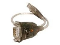
} // end of mainOk so I scoped my rs232 usb/serial adapter and I get 5.6 volts with my little cheep 2 chanal scope. Between pins 2 and 3 Transmit data and Recive data. And one of them to number one is the same the other is 0. This is all as I plug it in and unplug it. So is there a way to ping it and scope the ouput on the pins will I ping it? It is from a 5v usb powered new laptop... I dont think any usb/serial adapters would step up the voltage would they? Anyways it looks like this I swear its logitech but I can't find it on their website.
Attachments
OK so I figured out how to make a new C file in mplabX. So I started to make the file in note pad then posted it to Mplabx to a new C file and it will be edited as I learn the rest. But lets get the basics....
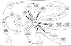
SO this is what I am looking at what would I need to add. And lets list where it goes by listing the function after what I want to do. So should it look like this???
This is only a start while I work on all the rest. I have ~9 days to work on this then back to work for a few months at 4days a week but over the next few days I want to get realy cracking at this so I am multi tasking.... Brainstorming how I want to make my code for the REAL DEAL as I work on the simple stuff!
SO this is what I am looking at what would I need to add. And lets list where it goes by listing the function after what I want to do. So should it look like this???
Code:
Read Throttle Position.  ADC function
Read hall position.      Read Hall function
Read Temp of motor.      Temp ADC function
Read temp of mosfets.    Temp2 ADC function
Read speed of motor.     Speed function
Read amps in phase.      Current Function
Watch interupt (brake) (or over amp shutdown) SD pin watch function
Calculate PWM based on above.   Main function
Calculate What phase to energize based on above.  Main function
Calculate Advance based on above.    Advance function
Energize PWM with set min off time.  Main function
Wait for x time Start over.         Main function
Loop forever                            Main function(while (1)?)
This is only a start while I work on all the rest. I have ~9 days to work on this then back to work for a few months at 4days a week but over the next few days I want to get realy cracking at this so I am multi tasking.... Brainstorming how I want to make my code for the REAL DEAL as I work on the simple stuff!
Then this is after I added it to MplabX (just a start)
Code:
#define  __p30F3010__
#include  "p30F3010.h"                 // put compiler dsPIC.h file in root
#include  "adc10.h"
#include  "delay.h"
//-----------------------------------------------------------------------------
//Configuration bits
_FOSC(CSW_FSCM_OFF & XT_PLL4);
_FWDT(WDT_OFF);
_FBORPOR (PBOR_OFF & PWRT_16 & MCLR_EN);
_FGS(CODE_PROT_OFF);
//-----------------------------------------------------------------------------
//Program Specific Constants
//Fcy = cycle clock = Fosc/4 = (XTAL * PLLmultiplier)/(4*PostScaler)
#define FCY             5000000        // 5 MHz Xtal*PLLof4/(4*Postscalerof1)
#define MILLISEC       FCY/10000       // 1 mSec delay constant


// Put global variables here
unsigned int ADCValue;
#define FPWM 20000		 // 20 kHz, so that no audible noise is present.
// subroutines or functions must be defined before they are used ===============
// subroutines or functions must be defined before they are used ===============
// subroutines or functions must be defined before they are used ===============
// subroutines or functions must be defined before they are used ===============

// void DelayNmSec(unsigned int N) =============================================
void DelayNmSec(unsigned int N){
   unsigned int j;
   while(N--)
    for(j=0;j < MILLISEC;j++);
   }
/*********************************************************************
/**Read Throttle Position.************************
/**ADC

// void ADC_Init() ==================================================================
void ADC_Init(void) {                  // functions must be defined before you use them
   ADPCFG = 0xFFFB;                    // all PORTB = Digital; RB2 = analog
   ADCON1 = 0x00E4;                    // Autoconvert starts conversion, auto sampling
   ADCON2 = 0;                         // sample CH0 channel only
   ADCHS  = 0x0002;                    // Connect RB2/AN2 as CH0 input in this example RB2/AN2 is the input
   ADCON3 = 0x0080;                    // Tad = internal RC clock (4uS)

   ADCSSL = 0;                         // not sure on this register, I will need to research it's effects

   IFS0bits.ADIF    = 0;               // clear ADC interrupt flag
   ADCON1bits.ADON = 1;                // turn ADC ON
   }

// ReadADC function =====================================================
unsigned int ReadADC(void){
   ADCON1bits.SAMP = 1;                // sampling begins immediately after last conversion
   DelayNmSec(100);                    // for 100 mS

   while (!ADCON1bits.DONE);           // conversion done?
      ADCValue = ADCBUF0;              // yes Now ADCValue holds the value for you to use
   return ADCValue;                    // Value of ADC
   }


/**Read hall position.*******************************
/**Read Temp of motor.*******************************
/**Read temp of mosfets.*****************************
/**Read speed of motor.*******************************
/**Read amps in phase.********************************
/**Watch interupt (brake) or over amp shutdown*********************
/**Calculate PWM based on above.**************************
/**Calculate What phase to energize based on above.*********************
/**Calculate Advance based on above.****************************
/**Energize PWM with set min off time.****************************
/**Wait for x time Start over.*******************************
Attachments
Disclaimer: *I'm a complete idiot at microcontroller code, so perhaps I should not even comment here.*
I have been researching various Field Oriented Control schemes, some which use sensors and some sensorless. There are existing code examples out there that look like they could be used as a starting point for a very advanced controller. While I would be clueless about writing the code from scratch, taking an example that's close and hacking on it is something that's more in line with my skill set.
Here's an interesting one, but no doubt very complex:
http://www.microchip.com/stellent/idcplg?IdcService=SS_GET_PAGE&nodeId=1824&appnote=en544825
The more I read about FOC, the more convinced I am that implementing it would not add that much to the cost of building a controller yet give much improved operation.
Running an induction motor would also be possible using the same hardware. The real hang up is getting the code right with all the parameters dialed in.
The example above is sensorless, and may not work well (or at all) at low speeds. For good low speed performance, it seems some kind of high resolution rotor speed sensor is the most economical route.
Thanks for the link Fechter.fechter said:Disclaimer: *I'm a complete idiot at microcontroller code, so perhaps I should not even comment here.*
I have been researching various Field Oriented Control schemes, some which use sensors and some sensorless. There are existing code examples out there that look like they could be used as a starting point for a very advanced controller. While I would be clueless about writing the code from scratch, taking an example that's close and hacking on it is something that's more in line with my skill set.
Here's an interesting one, but no doubt very complex:
http://www.microchip.com/stellent/idcplg?IdcService=SS_GET_PAGE&nodeId=1824&appnote=en544825
The more I read about FOC, the more convinced I am that implementing it would not add that much to the cost of building a controller yet give much improved operation.
Running an induction motor would also be possible using the same hardware. The real hang up is getting the code right with all the parameters dialed in.
The example above is sensorless, and may not work well (or at all) at low speeds. For good low speed performance, it seems some kind of high resolution rotor speed sensor is the most economical route.
Yes I want to make this something amazing when done (if I am ever done :wink: ) So starting with another code and working from there is a good thing for me to learn from, I am not quite ready to write my own code... Although I can make changes and I am starting to understand whats going on.
So for now I want to get something running with the right safety net in place.... PHASE amps and FET temp monitering are two safety fetures on the top of my list for now. I will be working on a lot of various things with this and remember Fechter 1 month ago I knew nothing about C or any programing language!!!
Gordo
100 kW
fechter said:Disclaimer: *I'm a complete idiot at microcontroller code, so perhaps I should not even comment here.*
I have been researching various Field Oriented Control schemes, some which use sensors and some sensorless. There are existing code examples out there that look like they could be used as a starting point for a very advanced controller. While I would be clueless about writing the code from scratch, taking an example that's close and hacking on it is something that's more in line with my skill set.
Here's an interesting one, but no doubt very complex:
http://www.microchip.com/stellent/idcplg?IdcService=SS_GET_PAGE&nodeId=1824&appnote=en544825
The more I read about FOC, the more convinced I am that implementing it would not add that much to the cost of building a controller yet give much improved operation.
Running an induction motor would also be possible using the same hardware. The real hang up is getting the code right with all the parameters dialed in.
The example above is sensorless, and may not work well (or at all) at low speeds. For good low speed performance, it seems some kind of high resolution rotor speed sensor is the most economical route.
It seems to me that this is precisely what Lebowski has done? Use 3 HALL's for low speed operation and a sample of BEMF for timing and current control related to throttle position and delta wanted. He has gone a lot futher with the software to provide additional fail safe incase of throttle short, overvoltage etc. The plan is to piggyback the 30F on top of a standard Infineon controller of whatever insane current capability one wishes to control. That is what I understand from my reviewing the information provided?
Here is a code that compiles for me and its set for 20khz PWM. I want to add some things and maybe change some things. As Ricky pointed out make sure the safety items work first. What Im going to do is hook up 3 light bulbs in in Delta so I can use them as phase loads to first see it all work. Then as I get going I will add a motor.
I know Dave said its best to start from scratch but as I learn what all the code is that might take me another year.
I have a general understanding of the C laungauge and microchip programining so modifing code or writing some functions is what I feel is best for me for now.
But I am thinking I want to add current sensing to this code right off the bat. Anyideas?
Code:
#define __p30F3010__
#include "p30F3010.h"
#define FCY 10000000// xtal = 5.0Mhz; PLLx8
#define MILLISEC FCY/10000// 1 mSec delay constant
#define FPWM 20000          // 20 khz
#define Ksp 1200
#define Ksi 10
#define RPMConstant 60 *(FCY/256)
#define S2 !PORTCbits.RC14
void InitTMR3(void);
void InitADC10(void);
void AverageADC(void);
void DelayNmSec(unsigned int N);
void InitMCPWM(void);
void CalculateDC(void);
void GetSpeed(void);
struct {
unsigned RunMotor : 1;
unsigned Minus : 1;
unsigned unused : 14;
} Flags;
unsigned int HallValue;
int Speed;
unsigned int Timer3;
unsigned char Count;
unsigned char SpeedCount;
int DesiredSpeed;
int ActualSpeed;
int SpeedError;
int DutyCycle;
int SpeedIntegral;
/*************************************************************
low side driver table is as below. In this StateLoTable,
the Low side driver is PWM while the high side driver is
either on or off. This table is used in this exercise
*************************************************************/
unsigned int StateLoTable[] = {0x0000, 0x1002, 0x0420, 0x0402,
0x0108, 0x1008, 0x0120, 0x0000};
/****************************************************************
Interrupt vector for Change Notification CN5, 6 and 7 is as below.
When a Hall sensor changes states, an interrupt will be caused which
will vector to the routine below.
The user has to then read the PORTB, mask bits 3, 4 and 5,
shift and adjust the value to read as 1, 2 ... 6. This
value is then used as an offset in the lookup table StateLoTable
to determine the value loaded in the OCDCON register
*****************************************************************/
void _ISR _CNInterrupt(void)
{
IFS0bits.CNIF = 0; // clear flag
HallValue = PORTB & 0x0038; // mask RB3,4 & 5
HallValue = HallValue >> 3; // shift right 3 times
OVDCON = StateLoTable[HallValue];// Load the overide control register
}
/*********************************************************************
The ADC interrupt loads the DesiredSpeed variable with the demand pot
value. This is then used to determing the Speed error. When the motor
is not running, the PDC values use the direct Demand value from the pot.
*********************************************************************/
void _ISR _ADCInterrupt(void)
{
IFS0bits.ADIF = 0;
DesiredSpeed = ADCBUF0;
if (!Flags.RunMotor)
{
PDC1 = ADCBUF0; // get value ...
PDC2 = PDC1; // and load all three PWMs ...
PDC3 = PDC1; // duty cycles
}
}
/************************************************************************
The main routine controls the initialization, and the keypress to start
and stop the motor.
************************************************************************/
int main(void)
{
LATE = 0x0000;
TRISE = 0xFFC0; // PWMs are outputs
CNEN1 = 0x00E0; // CN5,6 and 7 enabled
CNPU1 = 0x00E0; // enable internal pullups
IFS0bits.CNIF = 0; // clear CNIF
IEC0bits.CNIE = 1; // enable CN interrupt
SpeedError = 0;
SpeedIntegral = 0;
InitTMR3();
InitMCPWM();
InitADC10();
while(1)
{
while (!S2); // wait for start key hit
while (S2) // wait till key is released
DelayNmSec(10);
// read hall position sensors on PORTB
HallValue = PORTB & 0x0038; // mask RB3,4 & 5
HallValue = HallValue >> 3; // shift right to get value 1, 2 ... 6
OVDCON = StateLoTable[HallValue];// Load the overide control register
PWMCON1 = 0x0777; // enable PWM outputs
Flags.RunMotor = 1; // set flag
T3CON = 0x8030; // start TMR3
while (Flags.RunMotor) // while motor is running
if (!S2) // if S2 is not pressed
{
if (HallValue == 1) //IF in sector 1
{
HallValue = 0xFF; // force a new value as a sector
if (++Count == 5) // do this for 5 electrical revolutions or 1
// mechanical revolution for a 10 pole motor
{
Timer3 = TMR3;// read latest tmr3 value
TMR3 = 0;
Count = 0;
GetSpeed();// determine spped
}
}
}
else // else S2 is pressed to stop motor
{
PWMCON1 = 0x0700;// disable PWM outputs
OVDCON = 0x0000; // overide PWM low.
Flags.RunMotor = 0;// reset run flag
while (S2)// wait for key release
DelayNmSec(10);
}
} // end of while (1)
}
/*******************************************************************
Below is the code required to setup the ADC registers for :
1. 1 channel conversion (in this case RB2/AN2)
2. PWM trigger starts conversion
3. Pot is connected to CH0 and RB2
4. Manual Stop Sampling and start converting
5. Manual check of Conversion complete
*********************************************************************/
void InitADC10(void)
{
ADPCFG = 0xFFF8; // all PORTB = Digital;RB0 to RB2 = analog
ADCON1 = 0x0064; // PWM starts conversion
ADCON2 = 0x0000; // sample CH0 channel
ADCHS = 0x0002; // Connect RB2/AN2 as CH0 = pot.
ADCON3 = 0x0080; // Tad = internal RC (4uS)
IFS0bits.ADIF = 0; // clear flag
IEC0bits.ADIE = 1; // enable interrupt
ADCON1bits.ADON = 1; // turn ADC ON
}
/********************************************************************
InitMCPWM, intializes the PWM as follows:
1. FPWM = 16000 hz
2. Independant PWMs
3. Control outputs using OVDCON
4. Set Duty Cycle using PI algorithm and Speed Error
5. Set ADC to be triggered by PWM special trigger
*********************************************************************/
void InitMCPWM(void)
{
PTPER = FCY/FPWM - 1;
PWMCON1 = 0x0700; // disable PWMs
OVDCON = 0x0000; // allow control using OVD
PDC1 = 100; // init PWM 1, 2 and 3 to 100
PDC2 = 100;
PDC3 = 100;
SEVTCMP = PTPER; // special trigger is 16 period values
PWMCON2 = 0x0F00; // 16 postscale values
PTCON = 0x8000; // start PWM
}
/************************************************************************
Tmr3 is used to determine the speed so it is set to count using Tcy/256
*************************************************************************/
void InitTMR3(void)
{
T3CON = 0x0030; // internal Tcy/256 clock
TMR3 = 0;
PR3 = 0x8000;
}
/************************************************************************
GetSpeed, determins the exact speed of the motor by using the value in
TMR3 for every mechanical cycle.
*************************************************************************/
void GetSpeed(void)
{
if (Timer3 > 23000) // if TMR3 is large ignore reading
return;
if (Timer3 > 0)
Speed = RPMConstant/(long)Timer3;// get speed in RPM
ActualSpeed += Speed;
ActualSpeed = ActualSpeed >> 1;
if (++SpeedCount == 1)
{SpeedCount = 0;CalculateDC();}
}
/*****************************************************************************
CalculateDC, uses the PI algorithm to calculate the new DutyCycle value which
will get loaded into the PDCx registers.
****************************************************************************/
void CalculateDC(void)
{
DesiredSpeed = DesiredSpeed*3;
Flags.Minus = 0;
if (ActualSpeed > DesiredSpeed)
SpeedError = ActualSpeed - DesiredSpeed;
else
{
SpeedError = DesiredSpeed - ActualSpeed;
Flags.Minus = 1;
}
SpeedIntegral += SpeedError;
if (SpeedIntegral > 9000)
SpeedIntegral = 0;
DutyCycle = (((long)Ksp*(long)SpeedError + (long)Ksi*(long)SpeedIntegral) >> 12);
DesiredSpeed = DesiredSpeed/3;
if (Flags.Minus)
DutyCycle = DesiredSpeed + DutyCycle;
else DutyCycle = DesiredSpeed - DutyCycle;
if (DutyCycle < 100)
DutyCycle = 100;
if (DutyCycle > 1250)
{DutyCycle = 1250;SpeedIntegral = 0;}
PDC1 = DutyCycle;
PDC2 = PDC1;
PDC3 = PDC1;
}
//---------------------------------------------------------------------
// This is a generic 1ms delay routine to give a 1mS to 65.5 Seconds delay
// For N = 1 the delay is 1 mS, for N = 65535 the delay is 65,535 mS.
// Note that FCY is used in the computation. Please make the necessary
// Changes(PLLx4 or PLLx8 etc) to compute the right FCY as in the define
// statement above.
void DelayNmSec(unsigned int N)
{
unsigned int j;
while(N--)
for(j=0;j < MILLISEC;j++);
}bigmoose
1 MW
Arlin, I like the light bulb idea to limit current. I think you have 3 low inductance chokes laying around, add them in series with the bulbs to get some low level dI/dt going on. The bulbs will basically raise the R in the L/R equation. You can plot your new time constant with the graphing excel sheet.
Don't worry about my "understand all the steps" approach. I have criticized myself many times to Luke, saying how I have been ruined for low cost/fast development by my past life/experience. We could never use "something" just because it worked; we had to understand every little detail, and know every conceivable fault and the verifiable controls that were in place for that fault. As you can see, Luke and Methods are much better "solve the problem" on a budget and before you get old guys than I am. You will likely hit that home run and be years ahead of an iterative refinement type development approach! Go where your heart takes you, you will never regret it!
Don't worry about my "understand all the steps" approach. I have criticized myself many times to Luke, saying how I have been ruined for low cost/fast development by my past life/experience. We could never use "something" just because it worked; we had to understand every little detail, and know every conceivable fault and the verifiable controls that were in place for that fault. As you can see, Luke and Methods are much better "solve the problem" on a budget and before you get old guys than I am. You will likely hit that home run and be years ahead of an iterative refinement type development approach! Go where your heart takes you, you will never regret it!
Lebowski
10 MW
man that's some nasty noises that motor is making  maybe the guy could use some pointers from me
maybe the guy could use some pointers from me I know you are great at this code stuff and you are building some great things. But when you up the anti with a Lo-inductance motor and hi HP then you can talk. Untill then its just a miracle that anyone has a working Hi hp brushless motor of that kind of power level! You need to get a motor from marko and test with it. Don't worry about putting a load on it thats the easy part.Lebowski said:man that's some nasty noises that motor is making
Ok so Im building a quick power stage. With 6 irfb4115 fets only cause I have lots of them and this is for testing with no load at first. I forgot to put my gate resistor in line so im going back to add 10ohm resistor to each gate and what size of cap should I use? I might run this up to 100v but its just for very light load testing...
Attachments
Ricky_nz
10 kW
Which CAD programs that done in.
Any chance you can put a pdf or an image of the schematic up?
Any chance you can put a pdf or an image of the schematic up?
Its express PCB I just started to use it then big m posted up some stuff. I am almost done my power stage but how do I hook up the Isolated 12v power supplies? VDD is + from the Main board and runs tothe VDD on the IR2113 fet driver?
Then VSS is - from the Main board and runs to the VSS on the Ir2113?
Then VCC??? DO I take the Isolated power out of the isolated power supply to run VCC to pins VB and VCC? I take it the diode needs to be good for ~15v?
What about the isolated - from the isolated power supply? DO I tie it to VSS???
http://www.irf.com/product-info/datasheets/data/ir2110.pdf
Attachments
zombiess
10 MW
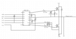
Arlo1, this is what I'm using to drive my paralleled FET stages. I stole this from an app note, but they had the SD and LIN labels wrong. SD needs to be tied to ground to enable the drive chip and a logic 1 to disable the chip. I read, re read and then read the app notes over and over to make sure I understood wtf was going on and I'm pretty sure this is what you want. You can omit the buffer that I have in mine and drive your FETs directly, but this buffer will drive up to 8A into the FET gates (lots of paralleled FETs) according to the app note and even more with bigger secondary FETs.
I haven't tested this yet, but it looks correct, hopefully it will help you out as it took me a long while to understand the chip and how to use it with all the different power supply voltages you can put into it and configurations it can run in. From the spec sheets and quick math I've run I don't think this circuit is going to draw much power at all, less than 1W. I need to go back and double check everything with the nC values of the FETs just to be sure, but I believe this circuit is sitting around 0.6W as is. This setup should allow you to supply it with just a single 15V power supply, but then your logic 1 needs to be close to 15V.
Why do you have the 15V zeners in your diagram and an SD connection to the phase output (are you planning some sort of driver shut down for over current output protection?)? You don't want to connect the SD directly to the phase output or bye bye driver!
Ricky_nz
10 kW
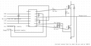
This is my one. also pretty much off the app notes.
0VD and 0VBus are tied together at one point only.
If you had 3 isolated power supplies you could use one per phase instead of the bootstrap circuit by removing D4 and connecting an isolated supply across C41 but to do this you need 3 completely isolated supplies around 12V (one per phase high side). This would have the advantage that your fets don't need to be switching to keep the bootstrap working to keep the high side powered.
Two of my phases have the ACS758 current sensors in the phase output.
The values are all messed up as this is taken from an early copy of the schematic but this circuit has been used up to 100A RMS / phase so far.
They specifically state that some of their earlier chips were more prone to latch-up and advise some measures to avoid this. I can't remember the app note number. Even though the chip i used is newer I put provision to limit the dv/dt of the VB supply pin. to avoid any unwanted latch-up.
My logic runs off a linear regulator powered off the +15V rail (actually set at 12.5 for various reasons).
The gate drive chip is an IRS21864
SD was just there to show if there was current sensing on the phase it could be used to trigger the SD pin. Its not going to be used just yet. And the zener is to protect the gate of the mosfet if the Driver ever fails. I did not install the Zeners it was just a thought I picked up from Shane Coltonzombiess said:Why do you have the 15V zeners in your diagram and an SD connection to the phase output (are you planning some sort of driver shut down for over current output protection?)? You don't want to connect the SD directly to the phase output or bye bye driver!
Lebowski
10 MW
Arlo1 said:SD was just there to show if there was current sensing on the phase it could be used to trigger the SD pin. Its not going to be used just yet. And the zener is to protect the gate of the mosfet if the Driver ever fails. I did not install the Zeners it was just a thought I picked up from Shane Coltonzombiess said:Why do you have the 15V zeners in your diagram and an SD connection to the phase output (are you planning some sort of driver shut down for over current output protection?)? You don't want to connect the SD directly to the phase output or bye bye driver!
The zener for the bottom FET is upside down.
Ok so I think I got it. I need to run the isolated 12 v to the hi side driver and the isolated negative to the phase wire to keep the hi side cap charged and the hi side driver 12v above the phase wire. And all other pins can be powered off the non isolated power. Each H bridge gets its own isolated 12v SD pin held to non isolated ground.
Attachments
Ricky_nz
10 kW
Yes that sounds right.Arlo1 said:Ok so I think I got it. I need to run the isolated 12 v to the hi side driver and the isolated negative to the phase wire to keep the hi side cap charged and the hi side driver 12v above the phase wire. And all other pins can be powered off the non isolated power. Each H bridge gets its own isolated 12v SD pin held to non isolated ground.
OK so I built a controller and a 6 fet power stage with 4115 fets I just have to go switch around the Hi side fets because i forgot that positive needs to be on the proper leg due to the internal diode.
What I need is to rip apart this code. I need to know what pins are for the on off switch and what else it will take to make it turn a motor.
Then as an open source project we are going to modify it and develop a code with all the features we can fit!
What I need is to rip apart this code. I need to know what pins are for the on off switch and what else it will take to make it turn a motor.
Then as an open source project we are going to modify it and develop a code with all the features we can fit!
Code:
#define __p30F3010__
#include "p30F3010.h"
#define FCY 10000000// xtal = 5.0Mhz; PLLx8
#define MILLISEC FCY/10000// 1 mSec delay constant
#define FPWM 20000          // 20 khz
#define Ksp 1200
#define Ksi 10
#define RPMConstant 60 *(FCY/256)
#define S2 !PORTCbits.RC14
void InitTMR3(void);
void InitADC10(void);
void AverageADC(void);
void DelayNmSec(unsigned int N);
void InitMCPWM(void);
void CalculateDC(void);
void GetSpeed(void);
struct {
unsigned RunMotor : 1;
unsigned Minus : 1;
unsigned unused : 14;
} Flags;
unsigned int HallValue;
int Speed;
unsigned int Timer3;
unsigned char Count;
unsigned char SpeedCount;
int DesiredSpeed;
int ActualSpeed;
int SpeedError;
int DutyCycle;
int SpeedIntegral;
/*************************************************************
low side driver table is as below. In this StateLoTable,
the Low side driver is PWM while the high side driver is
either on or off. This table is used in this exercise
*************************************************************/
unsigned int StateLoTable[] = {0x0000, 0x1002, 0x0420, 0x0402,
0x0108, 0x1008, 0x0120, 0x0000};
/****************************************************************
Interrupt vector for Change Notification CN5, 6 and 7 is as below.
When a Hall sensor changes states, an interrupt will be caused which
will vector to the routine below.
The user has to then read the PORTB, mask bits 3, 4 and 5,
shift and adjust the value to read as 1, 2 ... 6. This
value is then used as an offset in the lookup table StateLoTable
to determine the value loaded in the OCDCON register
*****************************************************************/
void _ISR _CNInterrupt(void)
{
IFS0bits.CNIF = 0; // clear flag
HallValue = PORTB & 0x0038; // mask RB3,4 & 5
HallValue = HallValue >> 3; // shift right 3 times
OVDCON = StateLoTable[HallValue];// Load the overide control register
}
/*********************************************************************
The ADC interrupt loads the DesiredSpeed variable with the demand pot
value. This is then used to determing the Speed error. When the motor
is not running, the PDC values use the direct Demand value from the pot.
*********************************************************************/
void _ISR _ADCInterrupt(void)
{
IFS0bits.ADIF = 0;
DesiredSpeed = ADCBUF0;
if (!Flags.RunMotor)
{
PDC1 = ADCBUF0; // get value ...
PDC2 = PDC1; // and load all three PWMs ...
PDC3 = PDC1; // duty cycles
}
}
/************************************************************************
The main routine controls the initialization, and the keypress to start
and stop the motor.
************************************************************************/
int main(void)
{
LATE = 0x0000;
TRISE = 0xFFC0; // PWMs are outputs
CNEN1 = 0x00E0; // CN5,6 and 7 enabled
CNPU1 = 0x00E0; // enable internal pullups
IFS0bits.CNIF = 0; // clear CNIF
IEC0bits.CNIE = 1; // enable CN interrupt
SpeedError = 0;
SpeedIntegral = 0;
InitTMR3();
InitMCPWM();
InitADC10();
while(1)
{
while (!S2); // wait for start key hit
while (S2) // wait till key is released
DelayNmSec(10);
// read hall position sensors on PORTB
HallValue = PORTB & 0x0038; // mask RB3,4 & 5
HallValue = HallValue >> 3; // shift right to get value 1, 2 ... 6
OVDCON = StateLoTable[HallValue];// Load the overide control register
PWMCON1 = 0x0777; // enable PWM outputs
Flags.RunMotor = 1; // set flag
T3CON = 0x8030; // start TMR3
while (Flags.RunMotor) // while motor is running
if (!S2) // if S2 is not pressed
{
if (HallValue == 1) //IF in sector 1
{
HallValue = 0xFF; // force a new value as a sector
if (++Count == 5) // do this for 5 electrical revolutions or 1
// mechanical revolution for a 10 pole motor
{
Timer3 = TMR3;// read latest tmr3 value
TMR3 = 0;
Count = 0;
GetSpeed();// determine spped
}
}
}
else // else S2 is pressed to stop motor
{
PWMCON1 = 0x0700;// disable PWM outputs
OVDCON = 0x0000; // overide PWM low.
Flags.RunMotor = 0;// reset run flag
while (S2)// wait for key release
DelayNmSec(10);
}
} // end of while (1)
}
/*******************************************************************
Below is the code required to setup the ADC registers for :
1. 1 channel conversion (in this case RB2/AN2)
2. PWM trigger starts conversion
3. Pot is connected to CH0 and RB2
4. Manual Stop Sampling and start converting
5. Manual check of Conversion complete
*********************************************************************/
void InitADC10(void)
{
ADPCFG = 0xFFF8; // all PORTB = Digital;RB0 to RB2 = analog
ADCON1 = 0x0064; // PWM starts conversion
ADCON2 = 0x0000; // sample CH0 channel
ADCHS = 0x0002; // Connect RB2/AN2 as CH0 = pot.
ADCON3 = 0x0080; // Tad = internal RC (4uS)
IFS0bits.ADIF = 0; // clear flag
IEC0bits.ADIE = 1; // enable interrupt
ADCON1bits.ADON = 1; // turn ADC ON
}
/********************************************************************
InitMCPWM, intializes the PWM as follows:
1. FPWM = 16000 hz
2. Independant PWMs
3. Control outputs using OVDCON
4. Set Duty Cycle using PI algorithm and Speed Error
5. Set ADC to be triggered by PWM special trigger
*********************************************************************/
void InitMCPWM(void)
{
PTPER = FCY/FPWM - 1;
PWMCON1 = 0x0700; // disable PWMs
OVDCON = 0x0000; // allow control using OVD
PDC1 = 100; // init PWM 1, 2 and 3 to 100
PDC2 = 100;
PDC3 = 100;
SEVTCMP = PTPER; // special trigger is 16 period values
PWMCON2 = 0x0F00; // 16 postscale values
PTCON = 0x8000; // start PWM
}
/************************************************************************
Tmr3 is used to determine the speed so it is set to count using Tcy/256
*************************************************************************/
void InitTMR3(void)
{
T3CON = 0x0030; // internal Tcy/256 clock
TMR3 = 0;
PR3 = 0x8000;
}
/************************************************************************
GetSpeed, determins the exact speed of the motor by using the value in
TMR3 for every mechanical cycle.
*************************************************************************/
void GetSpeed(void)
{
if (Timer3 > 23000) // if TMR3 is large ignore reading
return;
if (Timer3 > 0)
Speed = RPMConstant/(long)Timer3;// get speed in RPM
ActualSpeed += Speed;
ActualSpeed = ActualSpeed >> 1;
if (++SpeedCount == 1)
{SpeedCount = 0;CalculateDC();}
}
/*****************************************************************************
CalculateDC, uses the PI algorithm to calculate the new DutyCycle value which
will get loaded into the PDCx registers.
****************************************************************************/
void CalculateDC(void)
{
DesiredSpeed = DesiredSpeed*3;
Flags.Minus = 0;
if (ActualSpeed > DesiredSpeed)
SpeedError = ActualSpeed - DesiredSpeed;
else
{
SpeedError = DesiredSpeed - ActualSpeed;
Flags.Minus = 1;
}
SpeedIntegral += SpeedError;
if (SpeedIntegral > 9000)
SpeedIntegral = 0;
DutyCycle = (((long)Ksp*(long)SpeedError + (long)Ksi*(long)SpeedIntegral) >> 12);
DesiredSpeed = DesiredSpeed/3;
if (Flags.Minus)
DutyCycle = DesiredSpeed + DutyCycle;
else DutyCycle = DesiredSpeed - DutyCycle;
if (DutyCycle < 100)
DutyCycle = 100;
if (DutyCycle > 1250)
{DutyCycle = 1250;SpeedIntegral = 0;}
PDC1 = DutyCycle;
PDC2 = PDC1;
PDC3 = PDC1;
}
//---------------------------------------------------------------------
// This is a generic 1ms delay routine to give a 1mS to 65.5 Seconds delay
// For N = 1 the delay is 1 mS, for N = 65535 the delay is 65,535 mS.
// Note that FCY is used in the computation. Please make the necessary
// Changes(PLLx4 or PLLx8 etc) to compute the right FCY as in the define
// statement above.
void DelayNmSec(unsigned int N)
{
unsigned int j;
while(N--)
for(j=0;j < MILLISEC;j++);
}Ricky_nz
10 kW
Arlo1 said:OK so I built a controller and a 6 fet power stage with 4115 fets I just have to go switch around the Hi side fets because i forgot that positive needs to be on the proper leg due to the internal diode.
What I need is to rip apart this code. I need to know what pins are for the on off switch and what else it will take to make it turn a motor.
Then as an open source project we are going to modify it and develop a code with all the features we can fit!
Since S2 seems to be used to control what its doing (presume Switch 2 on some board) the following line looks like its read from Port C bit 14
#define S2 !PORTCbits.RC14
check the datasheet for the pin number.
Seems to be +ve logic, ie +V for switch pressed, 0v for switch released.
it does mention this is the start switch
Thanks ricky. I almost didnt even need to ask lol I just did not see that when I fisrt looked while I was tired last night.Ricky_nz said:Arlo1 said:OK so I built a controller and a 6 fet power stage with 4115 fets I just have to go switch around the Hi side fets because i forgot that positive needs to be on the proper leg due to the internal diode.
What I need is to rip apart this code. I need to know what pins are for the on off switch and what else it will take to make it turn a motor.
Then as an open source project we are going to modify it and develop a code with all the features we can fit!
Since S2 seems to be used to control what its doing (presume Switch 2 on some board) the following line looks like its read from Port C bit 14
#define S2 !PORTCbits.RC14
check the datasheet for the pin number.
Seems to be +ve logic, ie +V for switch pressed, 0v for switch released.
it does mention this is the start switch
OK I will go work at this for today.
Anyone know how to get samples from microchip? I tried and it says
Click on any of the underlined column headers to sort by that column
Microchip currently only accepts online sample orders from registered business or university email addresses. We currently do not accept orders from generic ISP accounts. Please do one of the following:
1. Register with a valid business or university email address and place your sample order
2. Visit www.microchipdirect.com to purchase parts
Thank you for your interest in Microchip.