OpenSource Remote for VESC ArduBoardControl

RollingGecko said:
Hi,

Unfortunately I never tried a boosted out yet. What is important in my point of view to have a defined center position. Hallefect is possible. But a poti is the most simple possible implementation and saves a lot of memory. Never the less I'm at the moment at 21K code which is 68% of the memory of the nano. We should consider to switch to another hardware. I've thought for the feather:

https://www.adafruit.com/products/2772

It is a 32bit system with 256 kB flash which is plenty for further improvements. And it runs with 3.3 V which is much better to use it only with one lipo cell. It has also a build in charging circuit.

When we will go for the configuration of the VESC over that device (I'm sure many people want to) I need to make elementary changes in the protocol stack of the radio communication. So I need to bring the message packaging that is used for the VESC from the RX to the Tx site. That will use also memory.

One further feature I want to have is also an SD card for telemetry recording. So we should have a slot for.

I like somehow the basic design of the nunchuk. Maybe we can adapt it? I've found on Grabcad a basic design of the nunchuk for solidworks. Maybe you can use it as a base?

https://grabcad.com/library/wii-nunchuk

I've seen also some implementation on the Blackberry pointing device on arduino applications. Maybe that could be a nice gadget for menu etc.

For the battery saving I will play around a bit on holidays. I want to make a timed option to bring the complete device in a sleep mode if not used for xx time. That would be good if you forget to switch it of. OLED and radio timeout could also be possible. So first OLED off, than radio and at the end the complete device in a sleep mode.

Regards

Andreas
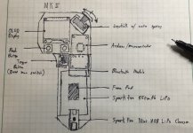
Take a look at some of the Texas Instrument boards as well. They have some pretty high end stuff and I have access to a ton of their hardware. I have also started sketching up some housing designs and I think it would be best to have it work with common off the shelf parts. ie. 3d print it and screw/snap parts in. I'll show you a few of my sketches once I clean them up and then start modeling in solidworks.
 
Here is a rough sketch of what I was thinking.
image.jpeg
Parts may be out of scale so proportions may be a bit different once I have exact measurements. Let me know what you guys think!

Note: I started looking into joystick/thumbwheel options and these look promising:
http://www.digikey.com/catalog/en/partgroup/cw-series/41392
 
s28400 said:
Note: I started looking into joystick/thumbwheel options and these look promising:
http://www.digikey.com/catalog/en/partgroup/cw-series/41392
$92 ouch!
 
Great piece of work!!

I have made a remote as well, using a nano and a nrf24l01+ (one in a modded nunchuck and one in my e board). I am using a hobby ESC right now but I have ordered a VESC and want to use the arduino to control it.

So I have downloaded your arduino sketches and installed al the libraries but I have a problem when I verify the sketcht.
The error I get is; 'CEPIN' was not declared in this scope.
For some reason the IDE does not see the config.h when verifying the code although I see the config.h tab in the cyan colored bar in the IDE.
I could manualy change the code by looking at the config.h and fill in the errors the IDE gives when verifying the code.

The config.h is in the same directory as the ino file.

Could you know what causes this problem?

Keep up the good work!!
 
rmrf said:
s28400 said:
Note: I started looking into joystick/thumbwheel options and these look promising:
http://www.digikey.com/catalog/en/partgroup/cw-series/41392
$92 ouch!
Whoops, didn't see the price on that. I saw ones for $5-$10 and thought that one was too. So not that one specifically, but that type of thumb wheel would work very nicely for what we want.
 
Hi,

Made just a short sketch based on the nunchuk. A bit wider in the middle to have a better fit for the OLED and a barrel roll wheel...

Nunchuk_wheel.JPG

Becomes maybe a bit more handy. Can print it out for a hand-test.
 
A bit to fat in the hand but in general a good approach...

2016-05-06 01.42.48.jpg
2016-05-06 01.42.51.jpg

@s24800:

Do you want to use bluetooth instead NRF24?
The loading chip would not be needed if the feather is used. It has already a charging circuit.
Please try not to make it to angular.
 
@RollingGecko

Yeah, I was just looking at the RF and Bluetooth modules. I think it would be better to use bluetooth as it is less prone to interference and allows for more options in the future. Perhaps a simple phone app could be done as well in the future.

I also noticed that the feather has its own integrated charger once I took a closer look at it. I have started a 3d model and am working on getting the parts as accurate as possible for planning. I will post some more info on this once I have a rough model done.

Ok, will do. The main thing I am going for is low profile so that it can comfortably fit in your pocket. I have based my model off of the sketch from earlier but I can tweak the aesthetics once I figure out the hardware placement.

Another note, I have been researching possible components to use as the wheel or joystick and I am not finding anything that really fits the bill. Since we are 3d printing the housing anyway, it might be best to design a simple leaver or wheel and attach it to a potentiometer or magnets and use a hall effect sensor. I kind of like the hall effect idea as it would be much more reliable although more difficult to implement. Perhaps we could start with a potentiometer and address this later.

Also, do you know how long that LiPo you have will last on a charge? It looks a little small. I can try to squeeze a larger battery into the housing if need be.
 
The idea was from the beginning to print the leveler and attach a poti. :)

The usage of a bluetooth module means a complete redesign of the radio stack. Then we can only go on with this approach because I will not maintain both. But it has main advantages. We can leave arduino on the receiver site away. But then I need to go in the VESC and implement some safety features if communication gets lost. But that is only a small topic.

There is a feather with a implemented bluetooth module:

https://www.adafruit.com/products/2995

Please don't forget the SD-card. We will need it to save setting after switch off. For example traveled KM. The feather has no EEPROM.
 
I have tried to verify the sketch on another computer. This time the IDE says it is missing a config.h in the VescUartControl library (I guess the IDE is saying it).
I have installed al the needed libraries.

The ouput from the IDE;

In file included from E:\longboard\longboard vesc arduboard controler\ArduBoardControler-master\ArduBoardControler_Rx\ArduBoardControler_Rx.ino:35:0:
C:\Users\User\Documents\Arduino\libraries\VescUartControl/VescUart.h:19:20: fatal error: Config.h: No such file or directory
#include "Config.h"
^
compilation terminated.

exit status 1

Edit:
I looked inside the VescUart.h. In the VescUart.h is this line #Include "Config.h", But there is no Config.h in the VescUartControl library. If I place the config.h from the RX sketch folder in the VescUartControl library, the verification and compile are successfull.
The verification was successfull but the IDE gave some output after the verification;

E:\longboard\longboard vesc arduboard controller\ArduBoardControler-master\ArduBoardControler_Rx\ArduBoardControler_Rx.ino: In function 'void loop()':

E:\longboard\longboard vesc arduboard controller\ArduBoardControler-master\ArduBoardControler_Rx\ArduBoardControler_Rx.ino:102:77: warning: large integer implicitly truncated to unsigned type [-Woverflow]

radio.writeAckPayload(pipe, &VescMeasuredValues, sizeof(VescMeasuredValues)); ^

C:\Users\lambe\OneDrive\Documenten\Arduino\libraries\VescUartControl\VescUart.cpp: In function 'int PackSendPayload(uint8_t*, int)':

C:\Users\lambe\OneDrive\Documenten\Arduino\libraries\VescUartControl\VescUart.cpp:139:21: warning: converting to non-pointer type 'uint8_t {aka unsigned char}' from NULL [-Wconversion-null]

messageSend[count] = NULL;

^

I dont know if the output from the IDE is normal.

Edit 2:

I think i have the same problem as Pedrodemio (post nr5 from this topic). Tried to fix it the same way as discribbed in this topic, still get the above error messages but the compiler completes.
 
I think 2.4 is better than bt. However bt for smartphone telemetry would be still a great thing (combined with jacobs app :roll: ). If it would be possible to connect an additional bt module on the rx side? dont know much about arduinos:/ Then we could also skip the oled and make even smaller and more stable remote.
 
RollingGecko said:
We can leave arduino on the receiver site away. But then I need to go in the VESC and implement some safety features if communication gets lost. But that is only a small topic.

There is a feather with a implemented bluetooth module:

https://www.adafruit.com/products/2995

Please don't forget the SD-card. We will need it to save setting after switch off. For example traveled KM. The feather has no EEPROM.

I like the idea of just using the VESC with a bt module but how would that be done without an arduino?

That feather looks perfect, I think it would be best to go with that as it is compact and has all the features we require

SD card in the remote? Would it be possible to have the settings save to VESC side instead? I think the VESC has memory on board for the settings. Do you think you could tap into that and then the remote could just be used to change the settings?

I think something like this would be ideal:

VESC Side:
All settings and info logged and saved here (Allows for different remotes to be used for the same board and also leaves the possibility for a phone app in the future)

Controller Side:
Code that looks at the VESC settings and allows user to change them. (Different power modes, whatever else)
Remote side code for calibration and testing (Calibration mode to test and calibrate thumb wheel and maybe adjust sensitivity)
 
I randomly stumbled on this video but this guy seems to be using bluetooth with the VESC and even has a cool logging phone app. https://www.youtube.com/watch?v=AAa55i9OPH8
 
It is really great that more and more people start to participate in this project. I'm curious where the project will go.

I defined for me now a roadmap:

For the first I will remain on my hardware to save some money.
I will first of all clean up the code because some things a really dirty. And a MUST is, that it can be compiled with the Arduino IDE.
In the next step I will redesign the radio implementation so that it can easily be adapted also to other hardware with a clean interface. Please contact me before you start implementing something.
Meanwhile I will also merge the OLED implementation to the main branch. At the moment the only problem is that some values are not valid. kmh and distance were calculated sick (I ride with 120-150kmh!?) and mah are not shown correctly.
And also as already said: POWER SAVING FUNCTIONALITY!!!
 
RollingGecko said:
One of the main key features I have to work on is a power saving function over timer and an alert. Killed the lipo because I didn't switch it of. F..k

Perhaps a buzzer could be added so it beeps when it gets low
 
s28400 said:
I randomly stumbled on this video but this guy seems to be using bluetooth with the VESC and even has a cool logging phone app. https://www.youtube.com/watch?v=AAa55i9OPH8

Hey @s28400 - that's me :) Saw your comment on the video, then saw this.

Bluetooth and the VESC is really easy, no arduino needed on the VESC side, just a UART to BLE bridge like the Adafruit UART friend. All my code and hardware config is here for you all: https://github.com/gpxlBen/VESC_Logger. The iOS code for VESC comms was heavily inspired by RollingGecko :)

If I can help with this project in anyway then happy to chip in. Keep up the great work!
 
@benj

Haha, I was just reading though your github and saw that you credited RollingGecko. Awesome lol. Unfortunately I am still waiting on my VESC's to get shipped as enertion is having major delays so I can't test the hardware just yet :( I'll definitely use that logging app when I build my new board though, saves me the hassle of carrying a laptop with me.

Yeah, if you see anything that you want improve upon, feel free to chip in. I'm trying to finish up the housing model so I'll post that asap.
 
Ok, so I have done a basic layout model of the remote. It still needs little things done like standoffs, screw holes and springs, but the general housing and layout is there. Let me know what you think. I figured this is a good point to make revisions if necessary.
[youtube]Lzt_KDR6STA[/youtube]

The following are included in the assembly:
Plastics:
-Housing side 1
-Housing side 2
-Trigger
-Thumb Leaver
Electronics:
-1x Joystick potentiometer
-1x Adafruit Feather Board w/ bluetooth
-3x tack buttons
-1x Adafruit 3.7v 1200mAh battery
-1x 0.96in OLED display
 
Alright, so I did a revision for mark II and switched out the screen for the larger 1.3in variant and also moved it to a better location. I think this is much better than the previous version. Also, there is plenty of room in the top above the trigger for LED's, sensors, or whatever. [youtube]i6yhbGvQOHs[/youtube]
As always, let me know what you think and any feedback or criticisms you have!
 
Back
Top