PING (KINGPAN) LIFEPO4 CHARGER FAILURE (RED LED ON)

fschoova

10 mW
Joined
Oct 27, 2014
Messages
20
View attachment 5Hello everyone,
Please forgive me for my bad english.
I decided to post on this fantastic forum to expose my ping charger(s) problem(s).
It seems that I'm not the only one in this situation.
I bought about two years ago LIFEPO4 batteries, one 48V15AH + two 24V10AH and diodes to possibly put them in serie.
I also bought 4 chargers, two 48v2AH and two 24v4AH.
I went about 100 times to work by bike, using a front wheel with a "ninecontinent" hub motor on a triban5. (80km per day)
Perfect till last month during which both my chargers stopped working.
I can confirm the problem because a friend of mine bought also last year batteries from ping and chargers 2AH and 5AH and that I could recharge my batterie with the 2AH one. The charger model is different, I can see trough the ventilation grid some component that I don't find on my own.
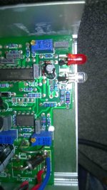
The first charger stopped working after about 5 recharges. The symptom is simply when connecting the battery the red led turn on but the recharge doesn't start. No ventilation, no burn smell, the circuitry is clean, no trace of burned component, the fuses are ok...
I tested the cables etc... The second charger stopped working after less than 100 recharge. Same symptoms.
I noticed that the "new" charger (from the friend) is working a bit differently as the red led does not blink when connecting the battery without the main power.
So I was planning to buy new chargers but I'm not convinced that the problem has no solution. Also when searching on the net I found many people speaking about the same symptom/problem but I was not able to find the solution.
What I found is that DNMUN expertise seemed quite relevant and I contacted him directly. He kindly advice me to post on this forum to maybe find a solution for all between us.
He also advice me to post pictures.
I jpeg compressed them while keeping a good resolution (some are blured).
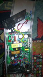
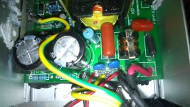
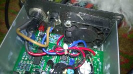
Here are some of them: please note that mess in the the white conductive paste is due to the removing of the circuitry from the aluminium box.
I can post other pictures, make some measurements... Thanks to all who can help to understand what happened.
Fred
 

Attachments

  • 2.jpg
    2.jpg
    214.1 KB · Views: 2,481
  • 5.jpg
    5.jpg
    267.6 KB · Views: 2,480
  • 8.jpg
    8.jpg
    318 KB · Views: 2,481
  • 11.jpg
    11.jpg
    184.9 KB · Views: 2,481
i noticed there is a fuse right on the circuit board next to where the two AC lines come in. you can see a cylinder with black heat shrink tubing around it. the trace says IN as i recall.

to test the fuse: with the voltmeter set to ohmeter scale, and AC power disconnected so there is no electricity inside the case, measure the resistance from one end of that cylinder to the other end. put you probes into the solder or just push on the wires sticking out.

see what the ohmeter reads.
 
no resistance, I tested it already last week but forgot to tell.
My ohmmeter says 0,6 Ohm but it is the same if I connect the two wires of the meter together, no resistance like any other fuse.
Tanks !!

I also checked below the circuit board, everything is clean and well soldered.
During one check, when I had put the power to check the small daugther board for tension, I suddenly noticed a spark next to the yellow coil (the big transformator) but cannot say exactly where it went. So I disconnected directly. (this on one of both).
Thank you again for your time and kindness.
 
so you have measured the AC voltage onto the circuit board? and did you measure the 340V DC that is across the rectifier diode and capacitors on the input? that is kinda hard too.

if you are getting AC past that fuse, it should get rectified for the transistors. the 340V will be between the two end pins of the rectifier diode bridge that is over on the side by the case. you have to remove the end plate to reach that end of the rectifier bridge.

the other end is next to the transistor under the clamp, just don't short the probe on the heat sink clamp, and in fact you can remove it right now so it is out of the way for testing the transistors too.

this spark was when you stuck the voltmeter probe in or while the circuit board was twisted?

the transformer thing was the one with 4803 printed on it or the toroid behind?

also we can remove that thyristor daughterboard if you use this on 120 always. that is simple to do.
 
yes I started to measure AC just after the fuse but nothing else. Not the 340 DC, I will do it this evening (I could have brought it here but I have to work :)
I was about to measure on the daughter board when the spark flashes, I stopped directly and removed the main plug.
We are here on 220V and yes if I could do without that daughter board, why not :)
Yes the 4803 transformer but no trace of burning or destruction, only le light, an ozone smell and the spark noise.
I will remove the clamp too.
I'll keep you informed.
Your instructions are clear :) thanks and have a bright day !!
 
ok, if you are on 240V then you have to keep that thyristor daughter board attached to the lid. it cannot touch anything else because it is at high voltage too. from the 240V.

the rectified 340V DC is across the two push/pull npn transistors under that clamp.

the legs of the transistor , looking from the front face, are: base, collector, emitter.

for an npn transistor, the higher voltage is on the collector and the emitter is at a lower voltage so the two transistors split the 340V between them with the emitter of the top transistor connected to the collector of the lower transistor. so the 340V can be measured between the collector of the top transistor on the right, which is connected to the top of the rectifier bridge along with the capacitor, and the emitter of the lower transistor which is connected to the - end of the rectifier diode and capacitors.

the left transistor is the lower voltage. you can see the base resistor right in front of the base. it has red, red, black, silver for 2.2 ohms. if the transistor blows up then it takes that resistor with it usually and yours do not look like they blew up so i think the transistors are ok.
 
I can also tell you that if I let the (not working) charger connected to the main and the battery, heat is dissipated from those transistors to the aluminium case.
As so as for the transistors on the opposite side. Quite the same amount of heat, reaching maybe 40°C or even more.
I hope to have time this evening to make the measurements for confirmation but I do think that there are NOT blown up.
Thanks again for your very clear and interesting explanations !
 
if they get hot then it is switching current. but you have no current on the output.

if you look in the middle of the charger, to the right of that toroid, there are 3-4 little black diodes with 207 printed on them.

use the 20V Dc scale on your voltmeter, put the black probe where it says - on the output in the back end, or place the probe on the loop of shunt wire itself which is also ground on the output. that will put the - probe at ground. so now the red probe can measure the voltage on those little diodes. put the red probe on the end of the diode where it has the white band, that is the cathode. it should have 20V+ present if the front end is switching. you may have to switch to 200V DC scale if it is over 20V DC.
 
Dear Dnmun,
I tested the 340V, I have something like 328DC on the bridge and between C and E of the transistors (like you said emitter from the lower and C from the top one).
No tension between - and cathodes of the diodes, nothing. If only main is connected the transistor seem to stay cold. I will connect the battery to see if it changes something, maybe I was wrong. I tested only one of both chargers. I try to do both.

I visited this site : http://www.avdweb.nl/solar-bike/electronics/portable-lightweight-lifepo4-ebike-battery-charger-800g.html#h0-1-2-5-the-battery-charger-circuit maybe it comes from one of your advices in an other place...
 
yep, albert reverse engineered the circuit diagram.

if you have 340V (323 is close enuff imo) then the oscillator should be making a little juice on those diodes because the TL494 IC has a small 3% duty cycle lower limit to maintain a little juice in the back end to power the ICs in the back end.

there are two sets of windings in the transformer, maybe you can see it on albert's drawing, and one set goes to the main output through the schottky diodes.

the other small winding carries juice out to those 4 diodes which make up a rectifier bridge that delivers current to the voltage regulator in the back end. it is over on the side behind the schottky diode under that clamp.

so if you have no voltage on that diode then the transistors in the front end may not be oscillating so they may be dead and the heat is from current passing through the shorted transistor.

to test the transistor, i use the diode tester. the tab on the back of the transistor is also the collector. the tab is therefore at high voltage so that is why it has that insulating rubber shield with the silicone heat sink grease on it. so you can use your diode tester between the collector and the emitter to see if the transistor is functioning as a non conductor when it is off. you can use resistance test for this too. put the red probe on the collector and the black probe on the emitter, and the diode tester should read open circuit. this is where removing the clamp is necessary so you can get one probe down to the leg of the transistor.

the base is the p part of the npn transistor. so there is a pn junction between base and emitter and you can measure it too, and then reverse probes and the pn junction will show open circuit since it is acting like a diode then.
 
ok :)
Yesterday I plugged the non opened charger to the main and after a while tested for the heat. No heat produced to the side of the transistors but heat produced on the other side where there are also TO looking like transistors (which are not transistors?)
On the opened one, I removed the circuit from the alu box and red on the TO which are indeed NPN (J13007-2)
I tested with a diode tester:
For Q1 and Q2 between B and C it is conductive in both directions (I swapped the probes)
Between E(RED) and C(BLACK) I read 665 on Q1 and 450 on Q2.
If I put the black on E and the red on C I read it is non conductive on Q1 but I read 468 on Q2.

All these with the transistors still connected to the circuit.
Also I noticed a small resistance on which the painting is slightly removed, the red red black in front of Q1 next to the capa.
If I try to make a measure directly on it it shows it is not conductive (the one in front of B of Q1), the other one next to Q2 is conductive :)
burned resistances.jpg
I hope it helps to confirm the death of the transistor.
I'm more and more confident that you will find the problem :) thanks again !!

Maybe it would be good to find an alternative for those transistors ?
Or do they need more dissipation/ventilation?
Ping said to me that there were problems of over heating with those chargers and that they changed the technology...maybe even following your own advices.
PCB.jpg
This evening I will open the second charger to check the same things.
 
the 13007 is an older transistor and the newer ones used are J13009 in the TO-220 package and there is a big one in the TO247 package that can handle even more current, maybe it is like 15A? i will look for pdf.

it is hard to measure 2.2 ohms but if it measures open circuit that is a clue it is burned. but it just does not look burned.

i have some of those too. if i can find them. the fourth band silver is 10%. this is a 1% accuracy resistors since it has the 4 color bands and the value is 10% of the indicated on the three bands. red red black is 22 times 10% so 22 x .1 = 2.2R.

you will see the pn junction between the base and emitter and the base and collector. the base collector junction will be a little lower in forward bias voltage because the collector surface area and doping is higher.

doping in semiconductors is good, not bad. the dope is the impurity added to the semiconductor to change it from an insulator to something that can carry current when it needs to.
 
It is always a real pleasure to read your comments so precise and instructive :D
Thanks !
If it is well the death of the transistors, do you understand why/how it happens?
I used to always connect the battery before the main power because I read somewhere it was better...
When connecting the battery there is always a spark in the plug and maybe I could add in the future the "anti spark circuit" of Albert (if important).
I'm already confident that it will work soon :wink:
 
always power up the charger first before connecting to the battery. the spark is the current going from the battery into the output capacitors on the charger.

if you power up the charger first then the output caps are already charged up so there is no spark and the connector is not damaged.

i have tried to tell people this for years now but there are people who just insist that i am wrong because they read it or have seen others do it on the internet. as though common sense is over ridden by someone posting anything they wanna on the net.
 
ok, I'll do that.
I suppose the best will be to change both the transistors and the resistance on both the chargers by j13009 ?
Is it good for the transistor?
http://docs-europe.electrocomponents.com/webdocs/12cf/0900766b812cf8af.pdf
from http://befr.rs-online.com/web/p/bipolar-transistors/8070899/
or this better?
http://docs-europe.electrocomponents.com/webdocs/00a6/0900766b800a6984.pdf

do you have a reference for the resistances?
it is 22ohm +- 10% but do you know how many watts?
I have 22Ohm 5% 1watt I think like this

about the same size but brown (milked coffee)
tanks again dnmun, I hope I don't push you :)
 
i had not seen that motorola part before. i bot some of the FJP13009 from mouser and i think they were about $1 each.

you can find them on ebay too.

you will need the 2.2 ohm, not 22 ohm resistor. it has to be the 1% too. everything should be replaced on both transistors then. both of the transistors and both of the base resistors, with parts from the same lot so the devices are balanced in performance.

lemme know if you want me to mail them. postage would be not too bad.

also i just remembered, wikipedia has a page for the push/pull oscillator circuit so you can read that to see what those transistors do.
 
fantastic :)
I would buy from you with pleasure !
I just have to check the second charger to see if it is the same problem and let you know.
Thanks again
 
if you can test the transistors on the second one without removing the circuit board from the case it will be easier.

if you unscrew the clamp and put the red probe on the tab at the top, then the black probe on the emitter which is on the end, you can just barely reach the emitter leg.

just make sure power is disconnected.

too bad other people over there don't already have some spare parts like this from repairing chargers themselves. you are one of very few people who has tried to repair the charger even though it is pretty easy to do.

but most, in fact seems like all, of the people here just go buy a new charger and complain about cheap chinese......

chinese would say lazy western richie rich people. money to burn and no respect for work.
 
You are simply right and I love to see that people like you exist on this earth, teaching others in a so altruist way/manner, disponible and conscious, a true teacher :)
This is a wonderful positive aspect of the internet. Keep going like this, stay an exemple for others :wink:

I tested the bridge: ok 328V
the resistances are ok too 2,4 ohm
When checking for the main, as at first it seemed there were no DC on the bridge, there was a sudden flash around the legs of Q2, nothing exploded, just a big spark around all the legs. I will now measure the Q1 and Q2 and let you know.
I go back checking :)

B and C are conductive in both directions for Q1 and Q2, I suppose it is not normal, nothing from B or C to E in any direction.
Please tell me if I'm wrong.
 
if you follow the traces from the end of that rectifier diode, there may be a better spot where you can measure the voltage on the - end of the rectifier. it should be tied to the emitter of that first transistor because the emitter in the push/pull circuit is tied to the negative side of the oscillator.

so you could test the rectifier with a probe in the solder where the emitter leg of the Q1 is soldered down and the red probe on the collector of the Q2, which is the tab. so that would make it even easier to measure.

if you shorted the base leg of the Q1 to the - end of the rectifier there, it may have burned the base resistor open circuit. that would account for the spark since that end of the rectifier there is 0V. the base leg would have voltage on it from the oscillator circuit. about 50V as i recall.
 
I understand, you are right but I was just about to test the main in the entrance (red and black cables) when the spark flashed.
I just edited the precedent post to add the test of Q1 and Q2, just tell me if I've tested in the wrong way :)
 
ok, so you shorted the AC on the input.

if either of the transistors conducts from the collector (red probe) to the emitter (black probe) then the transistor is shorted.

when you think about how it works, there is a higher voltage on the collector, and lower on the emitter when in the circuit. this is the same as the mosfets in the controller or the mosfets in the BMS. the semiconductor acts as an insulator to prevent the current from flowing through the transistor. when current is injected into the base, it goes over to where there is a 'depletion layer' between the collector and emitter and the charge injected reduces the depletion layer so that current can now flow from collector to emitter.

so if you have either of the two transistors shorted, then both have to be replaced. if the base resistor still shows 2.2 ohms then it is ok, but if one of them on either of the two transistors is burned open then you have to replace both base resistors.

so check on the base resistors on the second charger. you can send me a pm if you wanna buy some of my Fairchild parts, and i can mail the transistors over to europe, maybe as cheap as they can ship it to you locally. you may be interested in the motorola part too. it seemed like a good candidate to replace the fairchild FJP13009 part with. but this is a fairly commonly used switching transistor for switch mode power supplies SMPS.
 
Maybe you are right and I shorted something because the resistance are not conductive at all anymore or m'I too tired??
from BtoE or CtoE red to black there is no conductivity for both Q1 and Q2, I still have to redo the measurements to understand sorry :)
I will do this tomorrow evening.
By the way do you know Chris Howell? I build his EV charger (EVSE) 3 years ago to be able to charge our Leaf a bit faster than with the small portable charger unit. The Guy is also very open and sharing... I use his system every day since, plugged on an arduino. As I see that you are in the topic :)
When I don't go to work by Leaf, I go by ebike, 20 times less consumption.
I'm going to sleep now, thanks again for your time.
 
neato. i have thought about building a J1772 charging adapter for my charging spot here using 240V AC and set up the charging signal to allow 30A 240V at each outlet. i have 4 duplex outlets so i would need to eventually worry about total load on my electrical service which is antique and only capable of about 100A total out to the driveway apron where the charging spots are.
 
Hi dnmun

about the connection of the battery before or after the main.

You will find on the Albert webside http://www.avdweb.nl/solar-bike/electronics/portable-lightweight-lifepo4-ebike-battery-charger-800g.html#h0-1-2-5-the-battery-charger-circuit
look on point 3: Charger modifications...

However, on friday I've done what you advised, connecting the main then the battery and indeed I had no spark...
 
Back
Top