possible to replace old 4-wire twist throttle w new 7-wire ? [YES !]

DTBAKER61

1 mW
Joined
Feb 9, 2011
Messages
13
Location
santa fe, nm
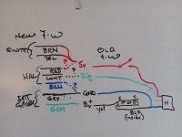
I am working on an old Prodeco with a 4-wire twist throttle. throttle failed..... return spring, switch, and signal all trash. I ordered a new one that had the same body, but it turns out to be 7-wire with different connectors than the original wich was just 4-wire with a single 4-pin connector. I was able (with some suggestions from @amberwolf ) to jigger up the new 7-wire throttle to work with the old controller which had the 4-wire connection ..... schematic and example in post #7.

01 old twist throttle.jpg

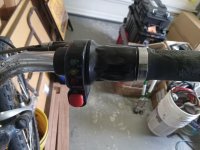
simple old twist throttle. No PAS on this old beast. the old throttle had 4-wire flat connector running to controller

02 red thru button to HAL.jpg

with internal jumpers between PAS/TAG button and HAL transducer... kinda hard to tell what was going on

03 jumper batt to HAL.jpg

the old transducer was so messed up I could really tell what was going on at first.
new one has 3 connectors and 7 wires to controller....

04 new 6-wire.jpg

so...... is it possible to connect the new 7-wire throttle to the old 4-wire controller? The colors are all different, so I am unsure.....

05 old-new internals.jpg

should I toss is the towel and buy a new controller ? (36v, 500watt)
this old bike does not have PAS, just twist throttle..... motor is a pin type connector.

20230529_motor connector.jpg
 

Attachments

  • 01 old twist throttle.jpg
    01 old twist throttle.jpg
    2.6 MB · Views: 0
Last edited:
FWIW, the hall doesn't usually fail-it's usually the switch (that connects 5v to the hall) that fails; something to check in your original if you haven't already. If this is the case you can take the swithc out of the new one and put it in the old one, straight swap, to fix it.

The way most of those 4-wire throttles with button switch are wired is the switch has the 5v input from controller on one side, and it's other side goes to the hall sensor's 5v line, then the ohter two hall wires are ground and signal output, to the controller. The fourth wire is battery voltage to run the LED battery meter (ground for the meter is internally wired to the hall ground, as the whole system's ground is the same).

The way most of the more than four wire throttle with button switch are wired is the switch has battery voltage on the input, then the output goes to the KSI (keyswitch / ignition, or doorlock, etc) wire on the controller. Then there's battery voltage (from that point usually) to the battery meter. Then there is ground, signal, and 5v for the throttle hall. That's usually five wires.

Yours with 7 wires separates the button wires out completely, so they would go to some connector on the display or controller that changes modes from PAS only to Throttle only or something like that. Then the battery meter has battery voltage and ground wires, and the hall sensor has 5v ground and signal wires.

So you can just ignore the switch wires if you don't need to use it, and connect the throttle hall wires up as normal--the throttle will always be live this way. If you want the safety-cutoff of the switch, just wire it like yours is, with one wire to the 5v, and other to the hall's 5v pin, disconnecting the 5v wire that's there now.

The battery meter you disconnect the separate ground wire and run one instead from the hall ground.


You'll want to verify this is how yours is actually wired first, but that's the common wiring.
ok, so I read thru your reply a couple times.... and I THINK I have a plan, but would appreciate your review. The one part that I am unsure how to verify or test is which of the HAL wires are 5v, sig, grnd since the colors do not match the old wires. What would be the most typical? The new has RED, WHT, BLU.

my proposed fix is to cut off the new connectors, and splice to the old 4-wire cable. let me know if this diagram looks right, and how I can verify the HAL wires to splice to old 5v, signal, ground correctly?
 

Attachments

  • 06 proposed splices.jpg
    06 proposed splices.jpg
    788 KB · Views: 3
I modified your diagram to show what the switch does, since your diagram shows the switch would be wired to not do anything, I think. Wasn't sure.
1685586468599.png
I cant' know if the wire colors in the diagram are the right ones to hook up, however--you'll have to trace those out from the connector pins to the actual components inside, on each.

The hall has two beveled edges on it's "front", so your wires need to go to the same place on the new hall as on the old one. Meaning, if the bevelled edge side is facing you, with the wires "down", then wherever the 5v goes on the old one, the 5v will need to go on the new one. And so on. This is a typical hall sensor pinout; yours is probably the same:
1685586862218.png


Wiring can be random, depending on what the colors were in a particular cable spool being used to create the wiring for a batch of...whatever.

Usually, throttle wiring (for just the throttle wires, no other devices on it) is red 5v, black ground, green signal, or white signal.

On potentiometer throttles it's usually black ground, blue 5v, brown signal.

But I've seen everything including all the same color wires for everything inside a device...

(which reminds me of....SG-1 Fail Safe:
Carter: Now find the wires leading from the timer to the detonator and cut the red one.
O'Neill: Carter, they're all yellow.
Carter: Say again?
O'Neill: There are five wires, and they're all yellow!
Maybe I should cut `em all.
CARTER: Uh, the thing is Sir, if you interrupt the wrong circuit it's basically the
same as telling the bomb that the timer's reached zero.
O'NEILL: I knew that.
CARTER: I'm sorry Sir, you're just gonna have to cut them randomly.
O'NEILL: Yeah, I knew that too.)
 
I modified your diagram to show what the switch does,
good catch on the switch.

the old transducer was damaged, so I could not really verify trace of colors for the 5v, Gnd, Signal. Is there any other way to verify from the leads? would I have to apply 5v+ and ground to what I think is correct and check for variable signal voltage?

regardless, I revised my sketch to clarify a bit.... and this is the current plan, unless you see a problem ?!:

06 proposed splices v2.jpg
 
Last edited:
For the hall, look at the diagram to see which pins are which, you can tell the shape of the case to see the pinout on your actual hall.

For the connector, plug it into your controller without the throttle/etc wired to it, turn the controller on, and measure the DC voltages you get on each one, with the black meter lead on your battery negative wire, marking them on your diagram for wire color.

If you can't see a difference in voltage between ground and signal wire, you can turn the battery power off, and use the multimeter set to continuity or ohms. Leave the black lead on the battery negative wire, and use the red lead to test the two zero-volt wires from the above test. ONe of htem will give a constant tone or nearly zero ohms reading; that is ground.
 
I didn't want to open up the new throttle body again (it was a bitch since I could not get the twist body to slide off), so I just tested 'as-I-went' while splicing. and...... it worked! Thanks for your help @amberwolf , you certainly got me going in the right direction. I'll be sending you a token of my appreciation for time saved.

I'll also go back to the top post to indicate solution for whoever digs up this thread in the future.

06 proposed splices v2.jpg

07 completed splices.jpg
 
I also noticed a sharp edge on rear axle was eating thru insulation, and *may* have been responsible for shorting battery voltage thru throttle, so I jammed in some plastic and taped it up just in case.

10 axle fix.jpg

11 repaired connector to 36v 500w motor.jpg
 
Glad it worked out. :) The axle exits often cause cable damage; phase wires that short to any hall wires can blow up a LOT of things, including the controller and anything powered by the 5v line, etc.

BTW, I recommend flipping the axle upside down from how it is now, so the cable exits downward, and then loops up in a J from there, as a drip loop to minimize water running down the cable into the motor. It's going to get in there anyway, but the less that does the better (you can't completely seal the motor up, and they are never fully sealed from the factory either. (in really wet conditons it's often better to drill a tiny hole (or set of them) in the side cover (not while it is installed!) right at the edge of the magnet ring/cover lip interface area, to let the water drain out (the hole just has to be placed at the bottom whenever you park).
 
Back
Top