power loss due to dirty connectors! anyone?

Vincenzo

1 W
Joined
Jun 12, 2022
Messages
61
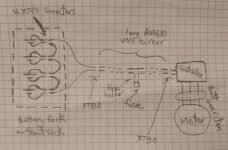
I have 2 xt90 connectors, 4 xt60 connectors and a blade fuse holder (and the fuse) between the battery and the controller, and there are three bullet connectors taken from EC90 male-female wires between the controller and motor. It took me a long time of observation to start thinking that all those connectors need some kind of contact cleaning (or vineger and baking soda, or something to remove the rust) or the bicycle starts loosing power (especially up hills) and sometimes at starting from stand still, there is a kickback for too much current causes lots of voltage drops in those connectors.

Searched in all forums and did not find anything relevant, does my thinking make sense? Did anyone have this issue? and is there a thread somewhere that I missed about regular cleaning?

Below is a primitive hand drawing that explains why I have all those connectors. Basically, ease of disassembly, diagnosis and repair.
 

Attachments

  • photo_2023-09-12_00-52-12.jpg
    photo_2023-09-12_00-52-12.jpg
    113.6 KB · Views: 18
Last edited:
Sure looks like the connector in your photo is a counterfeit. The real ones are not hollow like that in the middle. See here:

View attachment 339664
WOW!
That's a breakthrough!
That proves, for the first time in history, that there are two kinds of chinese, good chinese and bad chinese.
Unfortunately, the bad ones never get rich by saving some plastic here and there because the new plastic saving molds probably cost more than what there schemes gives them (By the way, there are bad Anericans who sell less plastic for more and call it "ultralight").

Did it ever occur to you that all the xt60's in the world look like the XT60 that you posted and all the XT90's in the world look like the XT90 that I posted?

I strongly encourage you to use google image search to look up "XT60 versus XT90".
If I'm wrong, I'll start my long journey looking for a good chinese who makes real and "genuine" connectors and will eventually find the good stuff that are a few milli-ohms less.
 
They are too good at making counterfeits, so it's difficult to tell visually. Looking at their website, it looks like AMASS makes several versions of XT90 and XT60 connectors, and it looks like the "H" version, as well as a couple others, have the hollow center. The "S" version (anti-spark) and a couple others have the solid center.


I don't see any major problems with the "before cleaning" contacts, so I doubt any of the issues are connector related.
I understand that there are ways to save a penny, like making the metal conductor from a cheap metal that cost less and cover it with some shiny paint, but for this application, I very much doubt that it's worth it.
We're talking about the very simple regular XT90's here, not the fancy/special ones you linked.

In any case, if the ones I'm using are counterfeit in a way that makes a penny for the maker (I bet everything that was ever made comes from the exact same location and address in china), they wouldn't have lasted this long. And, if they are anything but very efficient, they would've burned/melted a long time ago like some people commented here.

By the way, just looked at your bicycle. A piece of art!
 
Did it ever occur to you that all the xt60's in the world look like the XT60 that you posted and all the XT90's in the world look like the XT90 that I posted?
No not at all. Sorry I misjudged your photo to be of a xt60 so that's what I compared it to. Also sorry for derailing your thread-- now I am starting to agree with other posters here, I don't think your problems are caused specifically by your connectors.

You briefly mentioned you soldered them? using good solder? But what about the process? They can be tricky to get a good "fill." Sometimes you can get a cold solder joint in those cups, especially with the larger gauge wires. Any photos of the soldered connections?
And I'm sorry for my sarcasm again. I tried to take pictures of the soldering of the thick wires to the connectors but I couldn't find one that I did not cover with a double layer of heat shrink but trust me I have been soldering since I was 8 (a Weller was my dad's birthday surprise to me) and for the last few decades I've been using very fancy Hakko tools and doing soldering as part of my jobs sometimes. As far back as 2010, I had a job where part of my work was teaching adult professionals soldering. So, that's fine.
Chalo said a very interesting thing a few replies above about the throttle wiring, so I'm pursuing that in addition to probably disassembling and visually inspecting the driver PCB and the inside of the hub motor.
I did a ride yesterday and tried to see if the vibration happens with the pedal assist also, so i can eliminate the throttle wiring.
 
First, this is an amazing place for understanding throttle controllers: Guide to Hall Sensor Throttle operation, testing, and modification. - Electricbike.com Ebike Forum

I disconnected and inspected all the controller connectors and found out that the touching metal of those connectors is of a quality that less than car sensors' connectors that I used to clean and spray with the CRC red can electronic contact cleaner (from autozone, walmart, ...etc) at least once a year and feel a difference every time when I used to have a working car. Low current electrical bicycle connectors (sensors, brakes, displays, ...), after a year or two, turn dark gray or brown and need to be checked and cleaned periodically.

A relatively high resistance in one of those connectors may theoretically affect the function of what they are connecting but that, in my opinion, should be very obvious and very rare as they are either serial data (in the case of the display) or ON/OFF logic (as in the case of the brakes, or pedal assist if any, or speed feedback). The only complex signal (analog) is the Hall sensor throttle and if all of the three pins have a series resistances (corrosion, loose, contamination) of tens/hundreds of ohms, there should not be any real difference and after all my cleaning, I still have the friction/vibration situation at the highest throttle. The green/middle signal wire from the throttle goes to a very high input imedance circuit (most commonly input of an opamp) so it is relatively immune. If the black/ground wire has a seriously high resistance, throttle handle may not be capably of stopping the motor and that is a serious safety issue but I have a feeling that the designer put a remedy in the controller software for that. Lastly, the red/positive to the sensor and it needs to have a resistance of 5 or 10% of the total vcc-gnd hall sensor resistance to have a noticeable decrease in maximum speed (voltage divider).

I'm pretty sure, at this point, that my issue will come down to either that battery cells discharge curve becomes a little bit lower after 500-1000 cycles, or there's a mechanical deterioration of bearings or something similar to when you have sounds in a car's wheels and a shop does a balance/alignment job for your tires.
 
Back
Top