Pure sine wave inverter not powering 400W charger

NeilP

1 GW
Joined
Nov 27, 2010
Messages
5,012
Location
49.17303, -2.05354 Jersey, Europe
I have just acquired a solar setup, from a chap I helped a few years ago.
200W of panels
a PR1010 charge controller . Charge controller is designed to have panel, load and battery connected to monitor battery SoC
160Ah Lead acid deep cycle 12v battery
Inveter: Pure Sine wave 240 volt 600W continuous, 1200 W peak/surge

He always complained that the inverter would not run his BMS Alloy shell switched mode PSU charger.
Specs are,

600W lipo charger. set to 83 volts and 5 maps. Stand alone CA shows 400Watt going in to the battery.
Well, to be accurate it shows the 400 watt and the 5 amp charge when connected to the 240 house mains.


But if run on the inverter, it only puts out 0.5- 0.7 amps, 40-50 watts.


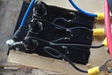
When I saw his initial wiring via a switch board and a fuse and the solar charge controller, I thought I had found the problem. The PR1010 solar charge controller is only good for 10 amps output...umm I thought..10 amps at 12 volt is not going to power a 600/ 1200 watt device.

So I now have the inverter connected direct with 8 gauge cable direct to the battery.

But still the inverter wont run the LiPo charger...well it runs it, but not at greater than 0.7 amps.

I have checked the inverter input current and it is drawing 4 or 5 amps with good battery voltage (13.4 volts ) at the inverter input. There is no voltage drop in the feed line from battery to inverter. Voltage at either end is within 0.01 volt.


Any idea what can be going on here? some incompatibility between a Pure Sinewave output and the Switched Mode PSU ?
 
Most likely it's not really a pure sinewave when loaded with that charger.

Do you have an oscilloscope?


If not, do you have an old higher-ohms (16ohm or higher) speaker and an old transformer out of an old low-voltage (3-5v) linear power supply, like even an old nickel-type cellphone charger? You can hook up just the transformer's AC input in parallel with the output of the inverter (while the charger is attached, too), and then put the speaker across the output of the transformer.

Then listen to the sound; a pure sinewave is a clear bass tone, but one with significant distortion or harmonics in it is pretty obvious in most cases, with little buzz or roughness to the sound, at the least.
 
Yes, I do have a scope, but been so long since I used it. last time I tried seem to remember it was dead. I'll need to dig it out.

If I can't get a trace on it I'll try the speaker method


I have been running other devices successfully from the inverter, two power over ethernet adapters, 240 volt to 12 volt and a 240 volt to 48 volt pus's to run a WiFi Access bridge and Access point and Sonos Zone Player3. All that runs fine.
 
If the charger is like mine it has a very poor power factor which makes it draw far more VA than the 600W rating of the inverter.

I monitored my charger with a Kill-A-Watt meter on the AC side and a Watts-Up meter on the output side while it was charging a battery. For a 191W DC output the charger drew 236W AC, however due to its very poor power factor of 0.62 it was also drawing 376VA. So if I were trying to charge at 400W the charger would draw an apparent power of 783W which is likely more than the 600W inverter can handle.


-R
 
I don't think so in this case. the inverter should be good for 600W with peaks surges of 1200W.

the input of the inverter is only drawing 50-60 watts from eh battery..5-6 amps or so.

i was expecting more like 50 amp or more draw at 12 volts if ti were to be outputting the full 600 watt or more
 
I would check the inverter with a resistive load, like 6 100W light bulbs, to make sure it functions as it should then I would reconnect the charger with the current output dialed way down to see if it works at all. If it does work at the lower current then dial up the current to see at what point the inverter no longer functions correctly.

-R
 
Hi Neil,
This is more boat based thinking from me, so take with a grain of salty water...
Usually the problem with inverters is on the DC side. Eight gauge wire is pretty small, and often the battery connections or ring terminals cause additional bottlenecks. I use a ten to one ratio for inverter loads: a thousand watts of AC will pull a hundred amps of DC out of the battery. Our voltage is only half of yours, so that calculation might be double what's needed? (The 240 volt file in my brain is unavailable at the moment.) Either way, a 160 amp hour battery is not big, particularly if not new. It may not be able to deliver fifty amps of power for long, also may have internal problems, like a failing cell.
I'd separate everything and load test, in real time. Get the panels and controller out of the picture entirely. Try to start an engine with the 160 battery (fully charged), repeat, headlights on, etc., or put a toaster-style load tester on it. Problems will reveal themselves as voltage drops, big ones. Put jumper cables from a running car battery on the inverter battery and see if anything changes, or power the inverter directly from a running vehicle. Get two or four gauge cables between the 160 and inverter, with no other connectors under the cable terminals.
This is just a quick guess, that the inverter isn't getting the juice it needs. Sorry if I misread anything you wrote, am on my phone working from memory...
--tp
 
technopeasant said:
Hi Neil,


Sorry if I misread anything you wrote, am on my phone working from memory...
--tp


Hi , thanks
Yes, all valid points, and along the lines I was thinking. You may have missed a fes bits I wrote, but I know the issues with replying on a phone , it is difficult, your response, appreciated either way. The only bit of relevance you may have not got , was that even under load there is virtually no voltage drop along the 12v DC supply cable.

I already upgraded TO the 8 gauge from what the original owner had. See the picture, below, this is what IT WAS running through, via a device with only a 10 amp output. The upgrade to the 8 gauge is a major improvement

This was the original wiring. But even with this removed and thicker direct battery connection, no improvement.

.

image.jpg

Batteries good, tested with load tester to 700 amps
I'll try with the resistive load next, it was on the list of things to try anyway. I am guessing AW maybe correct in the assumption of a not so pure sine wave interefering with and not allowing the unit to run correctly.
 
that is not really the issue,
I have at least three of these AC chargers....err OK,, two now :( I killed one and despite what other threads on the forum may say, up until now I have never had any issue in 4 years with BMS battery chargers,


The annoying thing is that I can't use it with this 'Pure Sine wave (allegedly ) inverter.
600 W Charger set yo output 400Watt, Inverter 600 with 1200W peaks...should be enough even taking in to account a LiPo charger with poor Power Factor.

I have confirmed that it is not a massive voltage drop or battery sag when running the inverter . Battery can output more than enough current. tested to 700 amps with a Lead Acid truck battery load tester.

OK 8 gauge is a little thin for a continuous load of 50 amps, but not so thin that it would stop the device from attempting to draw it


have to assume that it is just something to do with a Sw Mode PSU not being able to be run from an inverter
 
Yes, a dirty sine wave could/would cause problems. Also noticed there is no proud manufacturer's name on the front, just pretty picture, which seems unusual if from a good company.
Personally, I don't trust battery testers unless using resistive loads, hot wires, bubbles in the acid, etc. But you'll sort it out, I'm sure!
 
dnmun said:
8AWG is not adequate for 50A? where did that come from?

it is the thickest I had to hand, without cutting ym car jump leads in half...I say 8 gauge purely a guess, the copper core is about 3mm diameter. You can just see a length of it in red and black below the next picture.
I know it is not grea, but this wire I am using will take it for a short period. But either way..the inverter is not trying to draw the 50 amps any way and there is no readable voltage drop across the length, measured with the Fluke DVM The measured voltage at the inverter input as it was running the LiPo charger was 13.4 as was the voltage at the battery.

If you compare it to the wiring the original owner had it wired to, it is a massive improvement, even if not ideal.

this is how he had it wired

file.php
 
technopeasant said:
Yes, a dirty sine wave could/would cause problems. Also noticed there is no proud manufacturer's name on the front, just pretty picture, which seems unusual if from a good company.

I'll never know now where the original purchaser got it from. He was a chap I helped with an e-bike build when he lost his driving licence due to a brain tumour. He is no longer with us any more, and I was given it all by his wife. She did not need it and it was all in the way in the garage.


technopeasant said:
Personally, I don't trust battery testers unless using resistive loads, hot wires, bubbles in the acid, etc. But you'll sort it out, I'm sure!


Yes it is a big truck/tractor resistive battery tester, you could cook your bacon on the back of it :) if it did not have a timer. can draw up to 999amps
 
Well, replaced all the cables today, 10mm thick outer car/ truck jump lead cable.

As I expected, no difference.

Did some tests with resistive loads, a 600watt (or maybe 800, don't know what the bulb was) . It ran happily on a single smaller car battery , drawing about 30 amps as read on an inductive BluePoint clip on ammeter. could also just run a 200Watt soldering iron as well., with no voltage drop on the output


Tried again with the 600 watt LiPo charger, although it is set to 400 watt output. and inverter output voltage dropped down to 70 volts, though no alarm bleeper.


I then tried a 400 watt lipo charger from BMS battery. it was outputting 200 watt to the LiPo battery pack. that ran perfectly.

So I reckon it is a combination of a gutless unbranded inverter and a it not liking the switched mode supply. It is probably the power factor issue which I don't understand.

It will handle a 600-800 watt resistive load now problem, and output voltage stays up though alarm goes off if I ry over 800 watts
Only 228- 230 volts though. even unloaded it does not put out more than 230 volts :( should be 240,

But a similar 'on paper' load drawn by a switched mode pus and th output voltage drops down to 70 volts AC, the lip charger continues to run...and no alarm going off.
 
NeilP said:
Did some tests with resistive loads, a 600watt (or maybe 800, don't know what the bulb was) . It ran happily on a single smaller car battery , drawing about 30 amps as read on an inductive BluePoint clip on ammeter.

Is that a typo? That's only ~360W input, probably less than 300W output...
 
No, no typo

Definetly a 600 or 800 wstt halogen bulb

Definetly reading of 30 (lish) amps on the clip on type inductive ammeter.

But , thoae clip on ammeters, how accurate? No idea.

Also did not measure the AC current. The halogen bulb appeared to be producing a good output, but maybe it was not at 100%, no way to know.
 
Finally found my inverter manual. Unit is a nice Xantrex, 600 continuous, 1200 peak, modified square (made before the days of now-common pure sine wave inverters).
DC input needs four gauge wire, which is conductor about a 7-8 mm across. Terminals or wire should be mashed under tight nuts, etc. Battery should be no further than four feet away (eight foot round trip, pos plus neg). Also required is a charger (alternator or mains) with 25 with per cent of battery amp hour capacity (i.e., 50 amp). Many warnings about damaging AC driven charging devices (as opposed to AC to DC transformer powered). This should be less risk with a sine wave inverter, but who knows? This inverter: 12-14 VDC input desired, though I'd expect less output below normal charging level of 14 volts. Additional warnings about trying to run inverter without battery charging at same time (rapid battery depletion, low voltage alarms, etc.).

Methinks none of this may explain your unit's problems, but serves as a minimum installation guide. Anything less reduces output.

Most of the guidelines I've found online repeat the above. My opinion is that inverters are good for convenience but lousy for power.
 
NeilP said:
I have just acquired a solar setup, from a chap I helped a few years ago.
But if run on the inverter, it only puts out 0.5- 0.7 amps, 40-50 watts...
Any idea what can be going on here? some incompatibility between a Pure Sinewave output and the Switched Mode PSU ?
Hi Neil,

Congrats on your new solar setup. I've been powering my ebike on a similar setup since May 2000.

I'm not sure why you are trying to get this particular combo to work. :? Doing DC->AC->DC conversion, you are wasting close to 30% of the stored energy, a scare resource with solar cells. You likely have about 1000 Watt Hrs of energy to work with per day (200 watts X 5 hours). How much energy do you use each day in your ebike?

Why not just use a RC Lipo charger powered directly from the SLA battery? :idea: Good RC chargers are 90+% efficient, and are designed to run from a 12 volt car battery. There's 200 Watt Hrs per day right there just by making the switch to an RC charger. 8)

BTW, you want to aim for a C/20 discharge rate on that big SLA battery to avoid Peukert related losses. That implies that you need to draw about 110 Watts from the SLA when powering your charger, not 600 Watts... :shock:

My 180 AmpHr deep cycle SLA powers a 100 W charger. The battery charges all day in the sun, then I charge the ebike with solar power when I get home after dark. When the sun comes up the next morning, the cycle starts all over again... :mrgreen:
 
Holocene said:
I'm not sure why you are trying to get this particular combo to work. :? Doing DC->AC->DC conversion, you are wasting close to 30% of the stored energy,

For a feeling of satisifaction and 'duty' to my dead mate I got the kit from. I got to know him due his brain tumour and his wanting an e-bike. He could no longer drive and needed transport, so via chance meeting on a cycle path, I got to know him, and helped him build his bike. He already had a single solar panel (in his shed attached to his house, ) and beefed it up with a second panel, new batteries and inverter specially to charge his bike. He had mains power but wanted to see if he could 'go green'. He died last year, and never did get his solar system to charge his bike fully via the inverter.

I was about to go and buy new solar panel for my summer camp in the woods, then it occured to me his system was sitting, unused, in his shed. I phoned up his wife to see if she wanted it and she was glad to give it all to me and regain space in her garage and back wall of the shed where she had climbing roses. I could not just take it, she would not accept money, so I gave the cash to the kids.

I told him the same as you are telling me, about the dual conversion losses etc and got him to buy a Hyperion charger. It was the 14 series one, and he had a 14s pack, so no pack reconfiguration. He also had a 240 volt mains LiPo bulk charger.

At some point he killed the Hyperion, so could not even bulk charge with it, so he was back to charging with the switched mode 240v charger, but it never really worked and I never really got to go up and help him find out why.

When I dismantled his system and saw the charging / solar distribution panel he had built, all his problems with charging came back to me. Seeing his thin wiring on the fuse panel , as previously pictured, brought his charging problems back to me. I felt a pang of guilt that I never saw, with more than a cursory glance at the front of his distribution panel, this and helped him before he died.

He had wired the fuse panel to the output of the PR1010 solar controller, and then on to the inverter. PR1010 has max output of 10 amps ! and combined with that thin wiring as pictured on the fuse board, no wonder the inverter never supplied much power.

So out of my own guilt and in his memory and for a sense of satisifaction, I wanted to see if I could get it working.

But it looks very much like that even with my new thick wiring of two short lengths of truck/tractor jump start cable wiring and having the lead acid plugged in to a high power amp truck boost /start charger, the inverter will never have enough 'grunt' to run the switched mode bulk charger.
Makes me feel bad that I never looked at his system closer when he was alive and gave him the satisifacation too of knowing why it did not work properly.
 
Here is the thread from when John was alive

http://endless-sphere.com/forums/viewtopic.php?f=14&t=49495&p=734054&hilit=rivvy#p734054


I had forgotten about this thread until now.
 
Back
Top