QS v3, 72v battery, & Kinaye 12fet controller cutting out??

Tkseward

10 mW
Joined
Jul 8, 2016
Messages
32
Photo of project:


Hi first post on here and I need a bit of advice on what might be happening to my project I just got powered and programed.

So after going through the setup the bike has power to the rear wheel however it makes a loud torque knock on throttle start up and dies after a few seconds of throttle. I did this a few times and it throttled up for maybe 6-8 seconds and made a loud torque knock and stopped immediately.. now it just clicks once lightly on throttle and no power to the motor?? What the he'll is going on?

Setup:
QS v3 3000w hub motor
12fet 50v-90v 60a max speed controller (Kinaye Motorsports)
72v 10ah 50a constant
KT-LCD3 display (settings below)
  • poles = 32
    Motor phases = 3

Any ideas what I might be experiencing would be appreciated.
 
Update my display is throwing an error code "06" which is "motor or controller has short circuit abnormality".. how can I figure out which one has the short circuit.. the wheel still gets a quick blip of power to give a faint torque knocking noise, but that's it. Clueless on what the he'll happened..
 
Try to spin the rear wheel by hand.
If it is difficult to rotate the wheel then disconnect the phase wires and try to spin the motor again. Any change?
Yes = blown fets in controller
No = motor wiring
When first powering up a new install it is possible to hurt parts with too much throttle if the wiring is not correct.
 
I never looked inside one of those controllers to see the voltage rating of the parts inside.
Caps and fets are voltage sensitive. But may have a small amount of headroom built in?
The rotate the wheel test is to check for excessive drag.
If it rotates without a lot of resistance then stuff is likely ok.
If a phase wire is shorted to another phase wire or there is a blown fet then the wheel would be very difficult to spin.

Check the color combs of the phase wires and the hall sensor wires.
It is very rare that a direct match of the colors will actually be the correct set up.
 
Wiring is all correct.. it was giving power to rotate the motor but would die as if there was a fail safe limiter.. which suggests that the controller got fried.. I double checked the wiring and it checks out.. my gut is telling me that my 84.3v going to a 75v max controller according to Kinaye's description blew something..
 
Just to clarify I meant disconnect the wires between the controller and the motor.
The phase wires, they are the 3 large wires and then spin the motor.
In the first post you wrote that the controller is 50 to 90 volt rated.
Is anything rubbing on the wires where they come out of the axle?
How do you know that the wiring is correct?
 
I looked at wiring diagrams and I know phase wires because I build 3 axis gimbal at work. It does say 50v-90v on the controller, but on kinaye's description it says 75v max. He also gave worry that my battery voltage may be too high for the controller and said he was going to give me one of his higher rated controllers. I'll find out more once he responds to my email about this. However he never confirmed if he gave me the higher rated controller in previous emails.
 
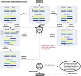
Phase-Halls Flow Chart.jpg

It doesn't feel good imo, but Barent at Kinaye sent me this diagram to experiment with... no fun :(


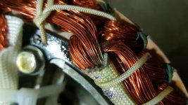
Think I may of found the problem.. the fuse blows now no matter which phase wire configuration I have.. the missing varnish looks to have caused a short? Any way to fix this or is this motor done?
 
20160708_231133-1600x900.jpg

Pulled backed shot. The rest of the windings have all the varnish/insulation intact expect that one area that looks burned.
 
Yeah, send pic to factory rep and ask what the options are. They might pay shipping and also replace for free, since it looks like a factory defect.
 
thanks for the tip. I have sent photos and my brief explanation of the motor malfunctions to QS Motor just before your response. Hopefully they can help me get this sorted.
 
I do not think that is a problem.
Under the white sleeve in the pic is where all 3 of the phase winding wire bundles are soldered together.
As long as the covers do not rub on the copper it`s o k.
To cover the exposed copper I have used brush on electrical tape with good results.

There is not much inside a motor to go wrong.
Hall sensors and poor connections are about the only problems possible.
Well that and maybe rust, or bad bearings, burnt insulation, loose magnets.... but only after use / abuse.

Controllers can blow up in many different ways.
Without a good known to work wiring combination it is time to experiment with the combos till a good one is found.
John in cr has written about his method of sorting out phase wiring combos and would be worth a read.
A good combo is a smooth quiet fast low amp draw story.
Bad combos are noisy, jerky or the wheel might just lock up and can draw big amps.
Enough to hurt a controller.
Do you have a spare controller?
Where in the world are you located?
 
I am in San Francisco.

I sent the photo and QS motor thinks it looks like a short. Still in the process of trying to figure out what happened.

it was spinning the first time i started it with loud noises.. it spun up fast and made a louder noise and completely stopped.. after that it never worked again.. after that loud noise every configuration of phase wires had zero effect, and it progressively got worse from there.. after trying all the phase wires combinations it started popping the in-line 5A fuses immediately after I plugged in the battery every time thus forward.

I'll check if it pops fuses without the motor hooked up which would point to the controller or somewhere else having a short I'm guessing..
 
I will. I'm in the process of trying to narrow down the issue. I will do a few more tests this week
 
Back
Top