QULBIX DIY Frame Q140MD

Andje

10 kW
Joined
Aug 25, 2010
Messages
779
Here's to a rough decade and a bit being over.

I have been ordering parts from around the world, and am now actually building and planning the details of this new vehicle.

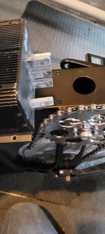
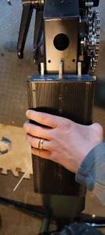
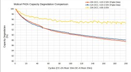
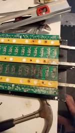
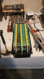
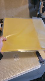
40s 3p (maybe 4p but I doubt there's room) of Molicel P42A 21700 cells 4200mAh, 10c.
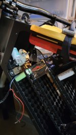
Kelly KHB14301HS 144v 300 amp.
DALY 40s 200 amp BMS
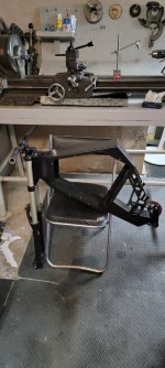
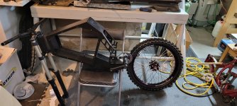
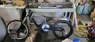
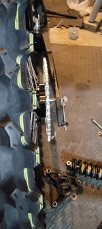
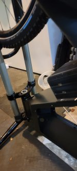
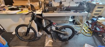
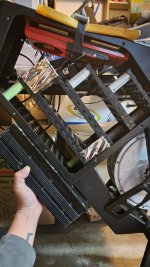
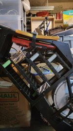
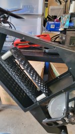
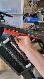
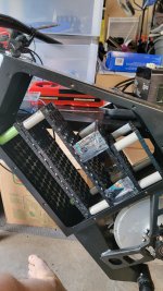
QULBIX Q140MD DIY Frame
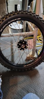
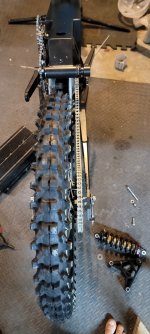
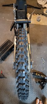
Surron SM Pro Platinum 19x1.4 with Mitas Pit Cross Terra Force MX 70/100-19 tire in the rear.
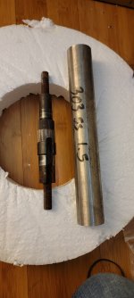
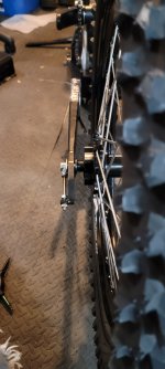
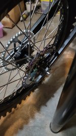
Crystalyte 5403/5404(from a decade ago group buy) depending on final gearing packaging restrictions. Custom stainless axles since the originals are made of pate at these power levels.
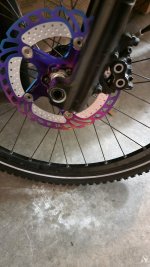
Boxxer World Cup triple crown front fork with Cane Creek ZS44m low profile headset.
Rear shock to be determined

The goal here is just to build the best thing that I can at this time. For me historically "best" has meant purely top speed, but I want this to also be jumpable and NOT BREAK ALL THE TIME.

Wish me luck.

20230517_135219.jpg
20230517_135308.jpg
 
44mm top and bottom zero stack pressed in. Crown race installed and forks secured.
 

Attachments

  • 20230523_150642.jpg
    20230523_150642.jpg
    975.6 KB · Views: 14
I mounted the rear tire today, and i picked up the peices of 303 stainless that will become the new axles.
 

Attachments

  • 20230524_164108.jpg
    20230524_164108.jpg
    2.2 MB · Views: 14
  • 20230524_164049.jpg
    20230524_164049.jpg
    1.1 MB · Views: 14
Heres the old axle and the new stock. Ill be changing some of the dimensions to fit the frame properly. For instance, the qulbix frame runs the rear swingarm off of bearings that rotate on the motor axle. The inner race is larger then the original axles are and would have required a sleave. Ill be able to turn that section of the axle to the appropriate diameter for those bearings, and the appropriate spacing for the chainline. Everything so far is working out for 420 chain to fit, sprockets should be here tomorrow/friday. The motor side one will need modification.
 

Attachments

  • 20230524_183008.jpg
    20230524_183008.jpg
    813.6 KB · Views: 6
Mocking it up and i realized i need a 220mm shock rather than this older one i had from a decade ago. So imagine it with a couple more inches and less hunched in the middle...
Good news is that although the controller is massive, it's naturally limited on the right hand side by the overdrive sprocket, so there's no puzzling about where it goes; as far back as it can without crashing into the pedal chain. In that position we see the top of the controller in a similar position to the stock controllers, although its obviously a bit thicker. It leaves what I'm going to optimistically describe as ample room to not be bottoming out the fork and front wheel into the controller. I might need to look at limiting the stroke or something, but I'm honestly hoping not to have to.
 

Attachments

  • 20230525_114152.jpg
    20230525_114152.jpg
    2.2 MB · Views: 28
Got some more parts attached. Looks like with my current axle the motor needs to sit flush with the brackets pedal side so the chainline is straight with the overdrive system. You could space the freewheel out probably 8mm or so and still have more then enough thread engagement with the freewheel. It looks like the sprocket side is pretty well aligned as is with this spacing, but i need to get the chain in the mail to know for sure. If it needs to move it has 5-8mm of potential adjustment in the outward direction.
Controller fits. Ill mill off the side brackets of the case and attach it through the bottom so it wont overhang the frame width by more then a few mm.
 

Attachments

  • 20230525_133012.jpg
    20230525_133012.jpg
    725 KB · Views: 15
  • 20230525_133008.jpg
    20230525_133008.jpg
    775.3 KB · Views: 16
  • 20230525_133053.jpg
    20230525_133053.jpg
    656.4 KB · Views: 17
  • 20230525_133118.jpg
    20230525_133118.jpg
    700.4 KB · Views: 16
  • 20230525_133125.jpg
    20230525_133125.jpg
    509.8 KB · Views: 15
Chain line looks pretty good with current dimensions. Might not have to make as many changes as i thought to the new axles.
 

Attachments

  • 20230525_163737.jpg
    20230525_163737.jpg
    930.1 KB · Views: 9
  • 20230525_163726.jpg
    20230525_163726.jpg
    613.5 KB · Views: 7
  • 20230525_163740.jpg
    20230525_163740.jpg
    935.1 KB · Views: 8
Here is it mocked up with the correct shock size. Ill probably go coil in the long run but i had this on hand...
 

Attachments

  • 20230526_115043.jpg
    20230526_115043.jpg
    2.1 MB · Views: 22
Welp... Had to buy the cells that were in stock, so I now have 210

Molicel P45B 21700 4500mAh 45A Battery​

on the way from IMR Battery. I was going to go for their younger brother at almost 50% the cost, but c'est la vie.
So hopefully I'll have 40s5p... 168 volt 22.5ah.

I'm excited to use the best cells available.
 
I just bought myself a frame and really enjoy looking at your build while i wait for mine!
 
Thanks!

I tidied up the workshop and got the lathe set up to turn the 303. Center drilled it and then took a couple light cuts to get the feel for the 303 on this Atlas lathe. Full speed with the tailstock properly locked with a center I was able to easily take off some material with my carbide tooling. Happy to see the finish feels smooth even without dialing in the feed rate (to change feed speeds on this lathe you change physical gears, and I haven't put in the effort yet as I haven't needed to thread anything).

Turn your sound down for this video, the lathe is super loud.
Atlas Lathe cutting 303 for replacement Crystalyte 5403 axle
 

Molicel P45B 21700 4500mAh 45A Battery​


I'm excited to use the best cells available.

Just a warning.
They are not the best cells available, (opinion) and they are not 10C contin... (fact) . Maybe some of the most hyped or most expensive ... I see alot of sag in them. I have built a few bikes with 10-20kW for sure. For instance, you would have to carry 2x the weight in the cell you just bought for the same power 1/2 the cell ( aH for aH) of the cells I like to use. I use a 15C+ contin cell.. of 25aH on my bike currently. 40,000 cycles plus, to 50% DOD, and ten years plus. It would take 12p of molicell to meet the same power out ( 50aH of the moli vs 25 aH of this cell for same power.. and if my cell has 50aH you would need 100aH ofd molicell ( 24p+) to get close to the power out.) I see people buy those Moli. IDK why they are so expensive but people like them.

Use them around 5C and they will last. Here is some ES user data ( PADJA!) of the cell you will use. You will not have many amps available without great sag. I have a friend with a Molicell 30s pack doing Grom shit ... and yeah its powerful but it sags 10-12v on a 80A hit... 4p 30s Moli. I could show those logs. He puts down about 20kW. I wouldnt be happy without 12-20p of the Moli... given I like instant tor key power that will throw you on your ass. Someone once asked me "Where did the P42 hurt you, Jean?" and I said " right in the wallet" .. lol.


Good luck with the build. Looks great. Will be d4eadly speeds.
 

Attachments

  • P42A Capacity Comparison.jpg
    P42A Capacity Comparison.jpg
    119.4 KB · Views: 4
They aren't rated 10c continuous, they are rated that up to 80 C. I agree this is marketing fudging the numbers slightly, but my BMS tops out at 200amps so 22.5 ah of these will be fine providing that almost continuous if I really wanted at least up to 80C pack temp. I don't know what kind of riding you do, but I will be mostly riding at 60kmph with burst up to 80, anything past that will be mostly for top speed testing. I won't be using 20kw continuously.
When I said best I just meant newest really. That chart from PADJA seems to be for the P42A which is not at all the same cell I have ordered.

Anyway, I will get some data myself. I have 2 old Hyperion 12 s chargers so I should be able to do charge/discharge on all these cells in 10 runs. I can get IR and capacity that way and match them well.
 
Welp lathe project is slightly on hold while a new crossfeed nut makes its way to me from the states.
At least I figured out where the chatter/inconsistency was coming from. It would maintain depth well as long as you were preloading it via the handwheel, as soon as there was room to move it would by a lot.
This is my first project on this lathe, so I'm not surprised to need to fix this. This nut has even been shimmed probably in an effort to slightly reduce the backlash.

Loose Crossfeed nut Atlas lathe
 
Thanks! I like it too, so much room for activities inside. It was a good fit for someone like me with old powerful hubmotors that could be used for mid-drive.
I'm hopeful this one repair to the Atlas will put me into good shape. The screw thread on the crosslide shaft looks pristine, and I bet this lathe has very few total hours on it. Someone probably crashed the crosslide into the chuck under power or something else that substantially damaged the nut at some point.
 
Cells got in today. Ouch on the import duties...
Im thinking about doing something like this configuration 40s5p. Bms mounts above pack to the top of the frame. Ths only issue is loading the pack into this spot, might require splitting it... ill have to tape some of these spacers up and try the whole chunk as a unit.
 

Attachments

  • 20230605_183156.jpg
    20230605_183156.jpg
    992.2 KB · Views: 20
Ok, so this battery configuration looks pretty advantageous, it is loadable as one unit, the included charger and on/off key ports aren't blocked, and plenty of room for the connections and auxiliary stuff (Cycle analyst shunt, contactor and main fuse). Easy to find space for the 12v pack that will provide power to the contactor and controller, and I ordered a 12v BMS for that today. the 40s BMS will even have room for it's cooling fan to circulate some air, although inside a semi sealed space of course... But could always flip it and cut out a section of the top of the frame for it to actually vent air externally, just would need to somehow waterproof that as much as possible.
Also showing where the controller will mount in one of these pics.
Now the INSIDE of the controller is a bit worrying now that i have it open. As you can see several of the parallel capacitor banks are either damaged from what looks like a component failure, or corrosion. The diagnosis is complicated because this controller was in my apartment when it burnt down about 10 years ago. It survived and I used it since then, but I wasn't surprised to see soot when i opened it, and i was immediately thinking it was damage from the fire, possibly gotten worse from corrosion over the last 5 years.
Now, let's be clear. I last used this controller about 5 years ago, and it went 135km/h with a 5403 hub motor on 36s10ah lipo. After looking at the damage to the controller, I'm pretty sure this was like this when it did that. I think that the first bank looks melted, and the second one possibly too. There is definitely corrosion where the heat cooked off the coating.
I think these cap sections are all in parallel phase by phase, so the others compensated for the one that are destroyed if this happened before the 5 year sitting period. It was inside for that period, so I wouldn't think it was a huge problem.
So. If I plug it in and it works, I'll basically ignore this damage I think. If it ends up being the thing that kills the controller, hopefully I can source another one. I guess I could also chance it and send it out to a generic pcb board repair place. The sections are all the same, so we could easily replicate the circuitry, worst comes to worst with a breakout board. I just dont want to blow it up testing it by turning it on if it is repairable unless I turn it on, you know... A call to anyone who has looked at the inside of Kelly controllers before, I would be very grateful for you opinion here.
Couple of pics here of the floating rainbow rotors as well. I needed the rear one for the Surron rear rim disk pattern which is not IS, and they come as a pair. Seem super gaudy to me but also kind of fun.
 

Attachments

  • 20230606_202808.jpg
    20230606_202808.jpg
    922.8 KB · Views: 25
  • 20230606_202228.jpg
    20230606_202228.jpg
    873.6 KB · Views: 26
  • 20230606_202329.jpg
    20230606_202329.jpg
    862 KB · Views: 25
  • 20230606_202318.jpg
    20230606_202318.jpg
    860.1 KB · Views: 20
  • 20230606_202356.jpg
    20230606_202356.jpg
    1.1 MB · Views: 20
  • 20230606_202405.jpg
    20230606_202405.jpg
    836.8 KB · Views: 22
  • 20230606_202238.jpg
    20230606_202238.jpg
    886.9 KB · Views: 23
Last edited:
In a dramatic effort of forsight, i bought the only other KHB controller availiable in the world off ebay this morning. Its a brand new in the box controller, the 200amp version of the controller i have, and comes with the j1 and j2 connectors and such. So if mine blows up i will be able to swap it off with minimal hassle and not have to rebuild wiring looms and such. Very satisfied with the outcome.
Been whatching a lot of pack building videos. The surron high power guys seem to have some of the most professionaly made packs that you can still get some insight into from their videos.
In settling on a single .2mm nickel strip with thin strips of pure copper 1mm pre-soldered down the center of the 2p nickel tape. My pack being 40s5p, i will have 5 cells in a line so the tape just spans the + and - of the 10 cells. The series current flows through all of them, so i either layer nickel or add copper. Layering just concentrates the resistance at the intial weld as far as i can understand the physics, so id rather reduce the overall pack resistance by adding thin copper, and presoldering it to the strips because i refuse to damage the cells with heat.
The layers wil be seperated by 1.5m electrical isolation board, and will likely be connected by large copper bus bars, bent in a vice jig to fit arround the pack. Im also hoping to have a bolted connection for the main + and -, properly mounted in delrin or something i can machine some simple slots into that is solid. 168 volts requires some proper thinking and isolation. Most of the wiring outside the pack will be 2/0 or 1/0 size cable.
Ill be using a small auxilary 14.8v pack to run the controller low voltage, so ill have 2 charge ports. The frame kit comes with a female port so i ordered the male side and a 14.8v charger to plug into it. The main pack will take a much larger anderson connector, still need to order the bike side of that and the housing to waterproof it. Not sure where that goes yet, possibly under the seat.
So a lot of mental progress. Im confident i understand the basics of the battery building. I need to finalise wiring, connector/crimped lug and heat shrink purchase. Kapton tape, fish paper... oh and a new multimeter mine died.
 
I think this is final battery configuration. Ill need to split the pack in the middle of the 4 stack to get it in and out, it just about fits in and out as one big peice but i think once it is welded and shrink wrapped and such it may not be able to make it. The bms fits easily in and out once the bat is in, and still plenty of room for the 4s2p aux pack and the fuses and everything. 40s5p for the win.
 

Attachments

  • 20230610_160504.jpg
    20230610_160504.jpg
    1.1 MB · Views: 10
  • 20230610_160440.jpg
    20230610_160440.jpg
    1 MB · Views: 9
  • 20230610_160424.jpg
    20230610_160424.jpg
    1.2 MB · Views: 10
Well thats a good question. As fast as possible.
The 5304 went 135km/h on 36s as a hub motor in a 26 inch rim. I own both a 5403 and a 5404 from the group buy 10 years ago. With the option of changing the gearing now i have a lot more top speed options to play with.
Currently i have a 19t and 22t front sprocket, and a 36t and 64t rear. So depending on combining those anything from 80km/h max with like 700nm of torque almost all the way to 80, or 130-150km/h with more like 400nm of torque.
I need to see what kind of riding im doing before i pick, because running the majority of your time in the 85% efficiency rpm range is really important for an air cooled motor. Gearing it at 150 and then running 60 all the time would probably be more like in the 30-40% efficient rpm range, and that will either overheat or at least reduce range substantially.
 
Last edited:
1.5mm glass fiber insulation board to make the interpack layers and isolate the bus bars that will conect the pacs.
 

Attachments

  • 20230612_124811.jpg
    20230612_124811.jpg
    686.5 KB · Views: 4
Received my new cross feed nut in the mail today, and it's the correct one and is tight on the screw. I need to get a new anchor screw to connect the two; the previous nut had been drilled and tapped for an m4 i think.
 
Back
Top