Re-wind of a turnigy 80/100 (Now-tutorial w/Video)

Another report....
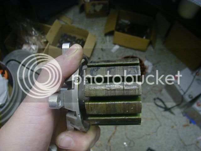
This re-wound motor is drawing 21 amps no-load on 44 volts...its got a ton of power but the controllers get HOT in 45 seconds & the Motor is hot also....

looking like another fail from my bench....no way this thing will last as it currently configured. I am afraid to hook my HV160 to it.....

any one care to speculate?

edit: I just sent an e-rant apology to AJ for getting his hopes up...I am getting tired of failure when attempting to spin outrunners with infineons....I am looking for more than current tech will allow, apparently...add that all the other parts of the system are just sh_t...(I have 2 more Hall throttles sitting on the bench that quit working that have never been on a bike), just pure junk.

All I want is a reliable 5000-watts for 30 minutes. I am totally unable to configure that with off-the-shelf parts in my price range...I can burst more power currently (hey a pun) but nothing that would compare to a real powered bike as of yet. If anyone thinks they have the answer I am all ears. Or better yet- build it & prove that it can be done with a video. Right now I will be betting on an overvolted hub motored bike to make the 12 miles of the death race...Or a $8000 budget on an RC build.

A pair of Astro's running on Castle controllers would prolly make the grade, but for that amount of money I can build 5 gasoline burning motor bikes that would withstand running at 100% for hours on end...what a frustration....
 
Thud. I feel your pain. I would try the Castle. It sounds as though your timing is off to me. (ease into the throttle to see where you are at.

Have you tried all 36 possible combos? When I was doing mine I found a wide range of no load amp draws. I was having probs with my 6 FET controller, I swapped in my 24 FET and it ran it well. However, it was real close in amp draw to my Brushed Etek at the same speed. I opted to go back to the Etek as it runs very cool. The Turnigy was getting up to 170F and I didn't like that.

I will run more tests as time allows
 
Thud I feel your pain to,
I really dont understand why you are having so many problems, One thing you might consider is 2x 3.25kw (aerodrive) with 2x 6fet controllers i.e 2X mysetup would be reliable for everyday use upto 8kw. I am waiting on some parts so I can start messing around with my big motor to join in the carnage of controllers :mrgreen: , also I did ask you in another thread ( i dont know if you seen ) what hall sensors are you using is it the 411's.
 
Guy's,
Thanks for the condolences. I am very confident I have the timing correct. There are...36 possible if you add the motor phase multiples...only 6 if you don't change your motor phase wires till you get it spinning in a direction....once it spins, its easy to change 2 phase wires & the same hall wires to get your direction correct.

This motor runs incredibly smooth on the 12-FET infineon. The re-wound motor cogs incredibly bad as compared to a stock wound motor...is this eddy current in my thick wire? I don't know. But when it gets that hot in one minute at a no load run, its a fail in my book. I have the hall's as perfectly placed as I can get them setting between the phases in the stator shimmed & epoxied in place. Perfect slow speed starting & torque.

The reason I blew a gasket today is that 2 hall throttle failures while testing on the bench...what a bunch of BS.

Oh yea Gwhy, I am using the honeywell 411a Jeremy recommended....
I did pick up a Hilliard kart racing clutch to play with as a mechanical amp limiter (like your scooter project) I have the pair of 18-FET Lyens controllers sitting on the bench...I just need to figure out how to operate it with A decent magura throttle. (or fab a better hall set up with a real moto throttle) The only schematic I have showing a pot throttle option is the 6-FET board. must be close to that on the other units.

The deeper I get into this, the more I am certain I am looking for way more performance potential than is reasonable.
 
Hi Thud

Feel your pain buddy!! I hate hall effect throttles threw all mine in the bin years ago, wont use anything other than Magura esp when my head is over the bars at 40mph anyway.

I must admit I did worry when i saw the thickness of the copper in there, maybe a strange effect going on with the low ir of the windings?or a nick in the insulation somewhere? you got that thing wound pretty nicely and its tight it may be the timing? can you move the halls to advance or retard it? can you try it with a xlyte controller? fully analogue controller? I have never had any issues spinning off fat winds with them but have had problems with the digital controllers.

Good luck with it, this will drive Kim back to drink for sure :twisted: I have a nice lemco in the loft if all else fails wont get hotter than a warm cup of tea at full tilt!!
 
That's bad news Thud,
are you sure you've wound it AacCBbaACcbB ?
Probably its getting hot from circulating currents?

A test with a sensorless controller would show the difference in no-load current, if it's misallignment of the halls.

Or you could measure the BEMF of each phase with a drill. This way you woudn't risk a controller.
-Olaf
 
The tattle here is being tough to turn by hand. The flux gap didn't change, and the magnets didn't get stronger. This means its energy being wasted in the windings. First place I would check is separating the delta connection, so its just 6 wires, and then feel the resistance to turn it by hand. If it turns free that way, then we know wye is the way to terminate these super low resistance winds. As phase resistance approaches zero, recirculating currents approach infinity, and circulating currents just become waste heat, and wye termination has no recirculating current.

Or, somewhere a wire is shorted to the stator or another wire. If you wanted to pass constant current through each phase, and read the voltage across them, that would tell you easily enough.
 
Good call, Luke.

My money is on a shorted turn, as this would give exactly these symptoms.

If you want to check what a shorted turn feels like, but amplified a fair bit, just short any two phase wires on an BLDC motor and try to turn it. You'll find that the cogging resistance rises dramatically.

Jeremy
 
Thanks Luke, I am trouble shooting right now....
Also, I am re-running the #s on the winding calculator looking for some balance.
I suppose its possible I have a nicked winding powering the stator...I will re-check (again)
the cogging doesn't feel like a shorted phase wires....but if I am shorted to the stator, that would be a new sensation for me...I am guessing your 100% right (I see Jeremys post is in agreement...poop! I have to fix this)
Questions-
1) experience winding 540 motors tells me a lower resistance wind will always draw higher amperage (& give proportional torque increases) What are the chances dropping the resitance from 14.3 down to 9.8 mOhms (by the drive calcultor readings) is creating this burden?

Olaf,
I was quite careful on the winding....this is the 3rd motor I've bothered to wind DLRK.

if I have to strip the stator for a re-do, I will go with a straight LRK wind & attempt to match the original resitance values of the stock motor......we need to be able to operate this with an rc controller after all. :wink:
 
Thud said:
Questions-
1) experiance winding 540 motors tells me a lower resistance wind will allways draw higher amperage (& give proportional tourque increases) What are the chances dropping the resitance from 14.3 down to 9.8 mOhms (by the drive calcultor readings) is creating this burden?
Todd,

The no load current will increase in direct proportion to Kv (inversely proportional to Kt). How much has this been changed?

Dropping resistance for a given Kt won't increase no load current....

[Edit: Ok, found it, 8 turns to 7 turns......]So, the no load current should only go up 1.14x due to that.
 
Computer glitch...I lost a post here & a pm I was writing.....some days are like that...... :evil:

Hello Miles,
I see you found it, but yes I fear my problem is a nicked wire energizing the stator.....
I checked it out with the Ohm meter before re-assembling...but something is definitely amiss.
(I am getting 21 amp draw in Wye!)

I used High temp epoxy for the re-assemble.....could be a real test to get it apart again.

Just for kicks here are the #s from a stock wind to the re-wind.
(all taken from Drive calculator)
Stock/Re-wind
R per coil: 21.5/14.6 (all R is mOhm's)
R in Wye: 43/29.3
R in Delta:14.3/9.8
copper in grams: 201/383

I am more concerned with reliability (concerning the controller) than a drag race motor that we need divine intervention to operate...
& Thank you to everyone who is looking at this & thinking out loud. Your input is keeping me from throwing all my electric bike stuff into lake Michigan in frustration. :mrgreen:
 
When you mentioned the additional cog force upon rewind, a flag did pop up for me. I would assume that it is either a short, or an improper wind.

Don't give up yet! You can get it going.
 
Thud said:
I used High temp epoxy for the re-assemble.....could be a real test to get it apart again.

That'll be a great mess :shock:

The laquer which protects the laminations could have become bad too, while you heated up the whole stator to disassemble it.
Can you measure the resistance between each lamination? If there are some shorted laminations you better throw it in the lake.
If it was my time, I'd consider buying a colossus 7kW kit and start with a clean stator. :?

-Olaf
 
I just played with simulating shorting motor windings and turning the motor. If you only short a single pair, it cogs similarly to the effect you would feel if the magnets were increased in intensity by a large degree.

I'm guessing somehow a pair or two of windings got shorted somehow during winding.
 
Sorry boyz, My winding skillz are impeccable :lol: ...however...I am curious what the stator lamination were insulated with.
Looks Like Olaf's summation was right on..

I re checked the whole thing 50 times with an Ohm meter & not a single issue with leakage...But after scratching some epoxy off the ends of the stator itself....It seems to be a dead short all the way through....no longer a laminated core but a solid, cogging nightmare......the feel is qute different than shorted phase wires. clean crisp cogging. not the semi smooth drag from a shorted coil.
I hasitly cut the windings....
skunkworksfloor.jpg


& re-assembled the thing with no wire on it...same super cogging... :evil: Now I need to separate the laminations & re insulate the bastage!
solidstator.jpg
 
Super bummer! Ouch! Looks like they must have used epoxy for insulation on the lams rather than the high temp oxide coatings used for insulation in some laminations. At least it's mystery solved now though, and it wasn't a problem with your beautiful windings. :)
 
Thud said:
& re-assembled the thing with no wire on it......same supper cogging.... :evil: Now I need to seperate the laminations & re insulate the bastage!
solidstator.jpg

Are you able to do this Thud? Least we know the cause, if you can fix this will you re-wind it with the same wire again?

I'm off to bed try to get some rest damn leg, hopefully might wake to some good news tomorrow morning haha...

Thanks ThudSTaR 8)

KiM
 
I still have the stator for the 80-100 that I gave up on if you need it. It got a little bent up while trying to get the stator loose from the bearing tube but if you think it might help in some way, just let me know and I'll send it out.
 
That would be cool mdd0127,
do you still have the address?
send a return address & I will compensate your generousity.... even if its lost a few laminations we can salvage it.
Thaks again.
T
 
I'll ship it out Tuesday.

As compensation for my generosity, just keep building cool stuff and pushing the envelope!

I'm happy to help in any way I can.
 
That would be great MD.

I delaminated the stator...not to bad a job really...heat gun let me slide a straight razor between the lams & put them out one at a time.....there was no way the stator was coming off in one pc :lol:
the last lam had a nice fillet of glue & was the hardest to remove.

Picture.jpg


Now to clean em up a lil bit, hit em with some hi temp paint...wait till the wife heads out to do some shopping & throw em in the oven for a dry to 300F temp...then its back on the arbor & re-laminating the stator...prolly with another wet spray of paint as a bonding agent...more Later

Oh yea...ther are 254 laminations that came off individually :twisted:
 
Too bad you took that apart allready.
My experience, the insulation between laminations isn't that great, and the aluminium that they are attached to could really have a big effect on resistance from end to end of the lamination, so measuring resistance isn't that great to determine if the laminations are bad. It doesn't take much resistance to stop eddy currents from propagating between laminations. I would be surprised if the heat gun you used disturbed the insulation between laminations, C5, which is typically used is good to 500-1000F and withstands heat anealing after stamping.

The best way to test the lamination stack is to re-assemble the motor without the copper windings and spin the thing by hand (or with a rope) and see how long it takes to slow down (or how hard it is to pull). Remember, at full rpm, that thing will have 140W of core loss, which is probably more power than your arm can produce!. So the motor should slow down pretty quickly when you stop pulling the rope, but it should not come to a dead stop really quickly, which it would if you just had a soild piece of iron in there.

Contact Mr. Lynn Girard at Polaris laser laminations if you want to get the laminations re-coated with C5 insulation, I haven't had them do any stacking or bonding for me before becauase that is a new service they offer, but in the past Lynn has been very good and fast in the past, next day quotes too.. http://www.polarislaserlaminations.com/. The other option is to re-insulate and re stack it yourself you can use locktite 290 which is a wicking bonding agent, so you can just paint it on after you have stacked things and it will turn it into a really solid piece. Locktite 290 is good for high-temp so it will work better than a wikcing grade CA, but CA would probably also be fine and is easier to find.

-ryan
 
Thanks for the info B,

I did the spin test after taking off the windings....this can & stator combo cogged at least 4 times worse than a wound motor of the same size...quite dramatic. I guess I will proceed with my current plan to insulate these...& re-assemble

I was interesed to see how some of the Lams were quite clean & seperated easily, other were really corroded.

this entire thread is essentialy "turd-polishing" so I will continue on...

While you're looking, I am going to re-wind this thing a little closer to the original resistance values & sacrifice some copper fill. Any other off the cuff observations or tips?

Thanks. T
 
Thud said:
Thanks for the info B,

I did the spin test after taking off the windings....this can & stator combo cogged at lest 4 times worse than a wound motor of the same size..quite dramatic. I guess I will proceed with my current plan to insulate these...& re-assemble

Must be cheap /quick manufacturing, they might not coat all the lams with bonding agent, and just use the wicking method that I suggested (which is much easier, but if you were making 100's of the things it would be better to automate a spray / stacking process).

On a side note, The term "cogging" is used to describe a few things, so it is best to avoid it and describe the force you measuring. Here are the things I have seen described as "Cogging" torque or force:
1: Most common: The force (or torque) required to move a stationary rotor from one lock up position to the next while there is no external load and no current running through the coils. This is often called starting torque in the generator world.
2: The force ( or torque) required to move a stationary rotor from one lock up position to the next while there is maximum current passing into the motor. This is more often called stall torque.
3: The variation in torque during a cycle while the machine is operating at maximum torque capacity. This is more often called torque ripple, and can be used for motor operation and generator operation
4: The amount of torque required to spin an un-loaded machine at some rotational velocity. This is more often called no-load torque (and is usually accompanied with a rotational velocity, i.e 0.8Nm @ 300RPM)
5: The observation of generally un-smooth operation of a motor or generator, ex, the motor has a bad cogging effect at low speed.

Thud said:
While youe looking, I am going to re-wind this thing a little closer to the original resistance values & sacrrifice some copper fill. any other off the cuff observations or tips?

Thanks. T

All the other motors / generators that I have taken apart have much more insulation between the coils and the stator. Usually combinations of kapton tape, Dupont Nomex 410, and sometimes Mylar. If you are going to use a little less copper this time, I would suggest better insulation. The problem with insulation is that it is a thermal insulator aswell. so the heat from the copper doesn't move to the stator as well. Having more copper in the machine is always better, if you are concerned that the resistance is too high, add some resistors externally (some copper wire, and maybe wrap it around a ferrite core to increase inductance aswell). You can easily remove the heat outside of the motor rather than producing it inside, and if you ever get a controller that can handle the low resistance / inductance you could remove the external resistors rather than having to re-wind.

I don't know your experience with winding, I imagine you have done a fair bit, so you probably already know this, but while you are winding, you might want to have a volt meter in diode checking mode (with the beep) handy and check the conductivity between the stator and the copper every couple turns. That can save you from completely winding a coil that you are going to have to remove and replace anyways. You can maybe even just un-wind a couple turns, add in some insulator and then keep going to remove the problem.

-ryan
 
Back
Top