Corrida victim
10 mW
- Joined
- Feb 27, 2020
- Messages
- 25
Hi everyone,
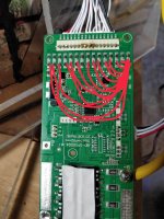
I couple days ago I received the famous smart BMS by LLT power. It worked flawlessly for a day, but after tidying up the balance wires (hot gluing and such), two cell readings are way off. Cell6 reads 47mV and cell7 reads 5.8v. And yes, I was stupid enough to leave the BMS connected.
I guess I must have shorted something without realizing with the hot glue gun, or it's just plain bad luck.
Anyway, here's what I tried:
At first I disconnected the wire between cell6+ and cell7-. There was no difference at all in voltage readings from the BMS, so I suspected this wire to be bad.
But:
- I measured every neighboring wire at the balancing connector (all read ±4.1v as they should)
- Measured every wire from the negative battery pole , and very wire gave a logical 4.1v increment. (4.1v, 8.2v, 12.3v....)
- Suspecting a high impedance from the cell6+ cell7- wire, I took a 47ohm resistor and connected it between that wire and an adjacent wire, expecting a voltage drop. But the multimeter still measured 4.1v
All in all, I'm pretty sure the wiring is just fine. So I guess the BMS itself is probably the culprit.
I know this BMS is quite popular in the modding community, so does anyone know of any repair guides? Schematics? Or is this a common issue? Any fuses/diodes that might have blown?