SOLVED: Blown Fuse on New Stealth Bomber Clone

igashosparks

10 mW
Joined
Jan 6, 2023
Messages
25
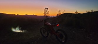
I just received my Stealth Bomber Clone from an outfit in China called Coolfly Bikes.

8000W QSMotor
SVMC72V100(M) Sabvoton sinewave controller
72V 41.6AH(China Battery)

On the trial run, going about 35MPH / 56 KPH, after riding for about 20 minutes.. all power died to the bike, display went dark after posting a 30H error code. After some initial troubleshooting, I saw that the fuse had blown on the outbound battery positive lead (between the battery and controller).

The response from the supplier is to replace the fuse.. I'm guessing about 120 Amps? My question back to the supplier was why did the fuse blow in the first place. (still waiting for the response, so I got up the courage to post the situation here, I'm pretty new to this.. and do not have a lot of electrical experience)

I was concerned that the controller at 100Amps is under spec'd, and I should have at least a 150Amp.. The supplier assures me, that the controller is not under spec'd.

Any advice, feedback, suggestions are most welcome. Thank you to any responses!

Blown Fuse.jpg

Cheetah Pro - Side View.jpg
 
Would a 41Ah pack really only be able to sustain 2C peak? maybe the BMS is too small/low limit for the pack?
Try to get more info from the battery pack manufacturer about continous and peak amps the battery/BMS can provide.
 
SlowCo said:
Would a 41Ah pack really only be able to sustain 2C peak? maybe the BMS is too small/low limit for the pack?
Try to get more info from the battery pack manufacturer about continous and peak amps the battery/BMS can provide.
That's what he did according to his post above mine, and the screenshots show that htey said it can only handle 6A (probably meant 60A) "normally", and 80A "continuously" (which almost certainly really means 60A continuous and 80A peak, as the other doesn't make any sense). Whether that info is correct or not it is difficult to be sure of.

Generic or low-quality cells could certainly be limited to low C-rates to prevent voltage sag / heating. Poor interconnections could also have those limitations. Recycled/salvaged & tested cells may also have much more severe limits than new ones, though better than the garbage leftover from that process that some manufacturers have used to turn into cheap garbage packs as noted previously. :(

The BMS could also be the bottleneck, as you note, in which case replacing it would correct the problem--but since it seems the battery manufacturer might not be able to reliably provide the info for the cells themselves (or we might not be able to clearly understand the answers they provide), it might not be easy to figure out the limitations of the cells to safely provide a larger BMS for them (or if it is safe to use a larger BMS).
 
I believe 60 Amp Max continuous isn't that uncommon from my surfing of what's available on Amazon for a 72v 41Ah battery.. it's definitely 60Amp, not 6.. the marketing guy confirmed as a typo. I mean, at 100Amp continuous.. I would only get ~40 minutes on a charge, no?

https://www.amazon.com/NBpower-38-4Ah-Lithium-Battery-Charger/dp/B07XHLWH13/ref=sr_1_4?crid=8XY0SKT45AKT&keywords=lithium+ebike+battery+charger+72V+8000W&qid=1672084262&sprefix=lithium+ebike+battery+charger+72v+8000w%2Caps%2C148&sr=8-4

【Parameter】 This PVC Ebike battery is 72V 40AH, suitable for 1500W 2000W 2500W 3000W 3300W motor. Max Constant Discharge Current: 60A, Charger: 84V 4A. Discharge Connector: XT60

I'm ok with that for now, at least to get all the other kinks out.. though a battery replacement will be in the not to distant future.
 
@amberwolf

I'm about to purchase the inline multimeter as you recommended: https://www.amazon.com/bayite-6-5-100V-Display-Multimeter-Voltmeter/dp/B013PKYILS

May I ask what you used/did to tap into the negative cable? Did you use a T tap? or something similar?

wire tap.jpg

t tap.jpg
 
igashosparks said:
I'm about to purchase the inline multimeter as you recommended: https://www.amazon.com/bayite-6-5-100V-Display-Multimeter-Voltmeter/dp/B013PKYILS

May I ask what you used/did to tap into the negative cable? Did you use a T tap? or something similar?
Note that the linked meter is just one possible unit to use for this purpose, posted as an example. It should work fine for the present (and probably future) testing purposes, though there are other types depending on your ultimate usage for it, if it's just for testing or will be permanently installed, etc., or if you end up needing one that can measure higher than 100A, etc.

I haven't installed mine yet (still using just the Cycle Analyst right now on the trike, which does the same job plus other things I need the trike to do), but once I do, it will be the same as the ANL fuse--it bolts inline with the cabling just like the fuse does, except that it goes in the negative wire rather than the positive.

The shunt has to go completley in the path of the current to be measured, just like the fuse does, so a T-connector from negative to it won't work. A T-connector *will* work on the positive cable, but I'd use a ring terminal to the fuse instead. (see below) This is partly because the T-connector can damage the conductors of the wire it taps into, and that's your high current connection to the controller.

So to install it, you would cut your battery negative (both wires if it is using small paired wires instead of one thick wire) wherever it is convenient / safe for placing the shunt physically within the frame/etc so you can protect it against shorting to anything, or any kind of mechanical damage, etc.. Then crimp ring terminals to the battery negative wires on each side of the cut. Those then get bolted to the shunt, one at each end. At this point, your crimps need to be very good, as bad crimps will cause excess resistance in the current path and cause extra voltage drop (and heating in the connector). (this is also true of the factory crimps, like those on the ring-terminals that bolt to the fuse).

For the thin wires from the shunt (and battery) to the meter itself, you can use whichever method you prefer, but I would again use ring terminals with wires crimped to them. This lets you use the same bolt points the shunt and the fuse use to connect to the battery itself, and the other wires from the meter to the shunt (as shown in the diagram below) also bolt to the shunt.

Alternately, you can insert all the thin wires that need to connect to the battery negative end into the ring terminal crimp along with the battery negative wire itself, before crimping, to then crimp them all together. Same for the controller-negative end of the cut. Then you only need a ring terminal for battery positive, that then bolts to the controller end of the fuse along with the controller positive.


If you have a stack of ring terminals (like the three that would end up at the battery negative end of the shunt), put the main battery cable itself on the bottom of the stack, at the shunt itself, so the high current path is shortest.

Make sure the flatwasher at the top of the stack fits entirely over the ring(s), so that it presses evenly over them all. It doesn't hurt to double up flatwashers on these, if there is bolt length available for it; the idea is to ensure the pressure from the bolt causes as complete a contact as possible for all the rings in the ring terminals to each other and to the contact surface below them, so that carries all the current, not the bolt (which is only a mechanical fastener, not a conductor).

The other ends of each of the thin wires go into the screw-down terminal block in the side of the meter case, so they don't need terminals on them, just a small amount of insulation removed (enough to allow full conductor contact inside the terminal block, but not leave any bare wire outside teh block.).

Let me know if any of that doesn't make sense or is incomplete. :) :oops:


https://m.media-amazon.com/images/I/61MOLfi2AmL._SL1500_.jpg
 

Attachments

  • 61MOLfi2AmL._SL1500_[1].jpg
    61MOLfi2AmL._SL1500_[1].jpg
    115.5 KB · Views: 86
igashosparks said:
I believe 60 Amp Max continuous isn't that uncommon from my surfing of what's available on Amazon for a 72v 41Ah battery.. it's definitely 60Amp, not 6.. the marketing guy confirmed as a typo. I mean, at 100Amp continuous.. I would only get ~40 minutes on a charge, no?

For a 41Ah pack, it could supply 41A for one hour. At 100A that would be 100 / 41 = 2.43x that rate, so it would last 1 / 2.43 the time, or 0.41hours. 0.41 x 60 minutes is 24.6 minutes. Or it could supply 20.5A for two hours, etc.

In reality it would last less time at the higher rate because there is more power wasted as heat in various places, instead of being used to move the bike. How much less depends on a bunch of things, so I couldn't give any estimates.

Most of these things aren't expected to be used at their maximum rates for their entire time, depends on the end-user's job requirements for the vehicle. Often they only see the max rate during acceleration while riding on a typical road, then drop down significantly during cruising.

In your usage, it's fairly likely to see higher average output than typical. How long it will be able to run between charges for your usage will depend on your actual power consumption, which is what the wattmeter should help you determine.


https://www.amazon.com/NBpower-38-4Ah-Lithium-Battery-Charger/dp/B07XHLWH13/ref=sr_1_4?crid=8XY0SKT45AKT&keywords=lithium+ebike+battery+charger+72V+8000W&qid=1672084262&sprefix=lithium+ebike+battery+charger+72v+8000w%2Caps%2C148&sr=8-4

【Parameter】 This PVC Ebike battery is 72V 40AH, suitable for 1500W 2000W 2500W 3000W 3300W motor. Max Constant Discharge Current: 60A, Charger: 84V 4A. Discharge Connector: XT60

I'm assuming this is just an example link of a similar pack?

None of that info comes up on the page when I view that link; Ctrl-F and then "parameter" doesn't find any instances of the word. :?

These are all the specifications I find on that page:
NBPOWER 72V 40Ah Lithium Battery,Ebike Battery with 150A BMS and 84V 10A Charger for 8000W Enduro Bike,8000W Ebike Kit,Ebike Motor.
Brand: NBPOWER
4.5 out of 5 stars 9 ratings
| 21 answered questions
Brand NBPOWER
Battery Cell Composition Lithium
Recommended Uses For Product Ebike,Power Tools
Unit Count 1 Count
Voltage 72 Volts
About this item

72V 40Ah lithium Battery
with150A BMS Continuous current
with 84V 10A Charger
Size:330*193*137mm
be used for enduro 5000W-8000W Ebike kit

Product Description

product specification
Cells: 18650 lithium cells
Size:330*196*137mm
Weight:17KG (battery+charger)
Charger:84V10A charger
Cycle Life:more than 800 times
BMS:150A Continuous current BMS
Composed Type:20S15P
Charge Current:10A
Max Charge Voltage:84V
Min Charge Voltage:60V
Certification:CE
Application:power Tools, Electrocar
Operating temperature:0℃~45℃(charge),-10℃~55℃(discharge);
Package content:
1)72V40ah Battery ;
2)84V 10A charger;
 
I must have sent you the wrong link to the amazon battery that has the continuous output at 60amp..

The one that I did link was the battery that I'm eyeing as a replacement:
NBPOWER 72V 40Ah Lithium Battery,
Ebike Battery with 150A BMS and
84V 10A Charger for 8000W Enduro Bike,
8000W Ebike Kit,Ebike Motor.
https://www.amazon.com/NBpower-38-4Ah-Lithium-Battery-Charger/dp/B07XHLWH13/ref=sr_1_4?crid=8XY0SKT45AKT&keywords=lithium+ebike+battery+charger+72V+8000W&qid=1672084262&sprefix=lithium+ebike+battery+charger+72v+8000w%2Caps%2C148&sr=8-4

I was finally able to log onto the controller via my bluetooth dongle purchased on AliExpress:
https://www.aliexpress.us/item/2255800719107444.html?spm=a2g0o.order_list.order_list_main.5.18751802NHR56k&gatewayAdapt=glo2usa&_randl_shipto=US

It worked right out of the box.. and connected right to controller.. as expected the builder didn't limit at the controller for an 80Amp max, 60Amp continuous battery It looks like it's just set on a recommended settings for a 100Amp controller.

controller settings.jpg

Next step is to set the controller to what it should be (I'll post when I figure that all out) I'll also have to go through and check the gauge of the wiring especially once I swap out the battery.
 
For the thin wires from the shunt (and battery) to the meter itself, you can use whichever method you prefer, but I would again use ring terminals with wires crimped to them. This lets you use the same bolt points the shunt and the fuse use to connect to the battery itself, and the other wires from the meter to the shunt (as shown in the diagram below) also bolt to the shunt.

Of course.. I didn't even consider attaching to the Fuse connectors for the positive cable... I knew I had to cut the negative for the inline shunt, but was stressing over having to cut into the positive cable as well. Makes perfect sense. I'll have to figure out a proper mount for the multi meter before I start cutting any wires.

thanks again for all the great advice.
 
I'm going to mark this one as solved.. Not sure if there is an official way to do that, for now.. I'll just change the title.

Ok.. So, I finally had received my BT dongle for the Sabvoton controller.. and was able to verify that the builder did not properly limit the controller to the max peak limit of the battery of 80Amp.. and instead installed an 80Amp fuse between the battery and controller.. with a 100AMP controller and a 8000W motor, obviously this wasn't going to work.. My first run out, I blew the fuse as soon as I got to a straightaway and opened her up.

After a very steep learning curve and lot's of help on this Forum.. (thank you Amberwolf!) I made the controller adjustment, dialed down the DC Current Amp to 80, replaced the fuse.. I also mounted the controller under the seat, which I might move back to the battery compartment.. seems like there is no real ideal spot to put it. I also upgraded the breaks to Tektro 725s, from the cheapo's that the builder put on.

I took Big Red up to Laguna Mountain, California.. outside of Pinnacles national park, some BLM land where the fire roads go on for ever.. I had a glorious 45 minutes of riding bliss.. 80amps was just the right amount power to get up almost the steepest of climbs, a little peddle assist coming at the hills with speed was enough to overcome. then.. fortunately and unfortunately, I stalled with a Hall Sensor errors on the highest peak on the way down.. so was able to coast back to my campsite.

The next challenge on this ebike journey will be to swap out the hall sensors.. I'll post about the experience, hopefully will be relatively straight forward!

20230210_095753.jpg

20230209_181407.jpg20230209_173541.jpg
 

Attachments

  • 20230209_180155.jpg
    20230209_180155.jpg
    2 MB · Views: 1
What temperature was the motor at inside when you got the hall sensor error? Given the hills, it's likely that the motor is overheating and that is causing the problem--changing the halls won't change this problem--that solution is more complex to determine (though probably simple to execute once figured out). (changing them will fix any that have failed from the heat, of course).

The other problem that happens from overheating is winding damage (insulation burns off, eventually shorting the motor and often blowing the controller), or the axle wiring (just inside the motor) may have it's insulation heat enough to allow phases to short to each other or to hall wires, or halls to each other, which can also damage the controller.

With heat it would make sense for it to fault on the downhill, as it takes time for the heat to soak thru the whole motor, and it might not happen during the climb itself.

Note that a number of motors of the size range yours is in have two sets of hall sensors, and two matching plugs, so you can unplug the failed set and plug in the other one. If they failed from heat then both sets will probably fail at the same time, so this isn't useful much of the time in these cases.


If you don't have a temperature sensor inside the motor, I'd recommend installing one while you're replacing halls. It might be tough to fit a wire for it thru the axle but if you're lucky there will already be an unused wire in the cable, so you can use the hall ground for one sensor wire, and the unused wire for the other one. You can hack a BBQ thermometer, or any of a number of purpose-made sensor/readout units for this purpose.

You can also use an IR gun to measure motor housing temperature on the outside, but it won't give you the actual inside reading, and there will be a significant time delay between changes on the inside and what you read on the outside.
 
Should I start a new thread or continue here?

I do not know what the temperature was at the time of failure.. nor do I see myself installing a sensor into the motor. but interesting, I really shouldn't be pushing at all the capabilities of the motor.. My max Amps coming through the controller is limited to 80.. so at 72V, that's 5760W max on a 8000W (allegedly) motor.. again, I I don't know all the nuance on what really constitutes an 8000W motor, what the heat factors may cause.. but, if I had a better battery, and hadn't throttled the controller down to 80AMS.. so say my max was 150Amps.. almost double, and I went full throttle.. what would have happened then?

I think I'm ready though to invest in a new motor & controller combo.. I'm pretty convinced that both of mine are of inferior stock.. if I can find a trusted supplier.. and perhaps a 3000W or 5000W. 8000 seems overkill.
 
If you were at full speed at the high power, the motor could probably handle it. If you're at lower speeds at that high power, especially very low speeds, the motor is wasting a lot of that power as heat inside it.

You can see how this works at the ebikes.ca motor simulator with any of the motors listed there that supports thermal modelling (has an "overheat in" field with a valid result when you run simulation). It doesn't really matter if the parts you pick there are anything like yours, just setup situations with different steep hills and run simulations that put it at higher speed and ones at lower, for the same full-throttle and motor/etc system. You can even use the A/B comparison mode to put them side by side.
 
Ah, that does make sense then.. So, the slower I go the faster I overheat at full load.. The Controller has a Motor Temperature Sensor and shutdown, but do not think there is an actual sensor in the motor.. so to your point about installing one. ugh!

Therefore, if I was pushing more AMPs, therefore maintaining a faster speed up those hills, I might not overheat? I'm using the simulator to the best of my meager abilities.. It looks like I would need to maintain a speed of 40Mph to never overheat, at full throttle.. (which wouldn't be feasible anyway from a safety perspective). well, that sucks.. the fire roads in this area have a lot of hill, and was the bikes intended use.

Well, I'm about to replace the blown Hall Sensor, FWIW, accept can't get the bottom part of the motor casing off.. I can't tell if it's due to needing to remove the freewheel.. or if I need gear puller to overcome the magnetic force. (or both)

(I'll start a new thread for that one)
 
Last edited:
Ah, that does make sense then.. So, the slower I go the faster I overhead at full load.. The Controller has a Motor Temperature Sensor and shutdown, but do not think there is an actual sensor in the motor.. so to your point about installing one. ugh!
Yeah, but if you're opening it up to replace the hall(s) anyway.... :)


Therefore, if I was pushing more AMPs, therefore maintaining a faster speed up those hills, I might not overheat? I'm using the simulator to the best of my meager abilities.. It looks like I would need to maintain a speed of 40Mph to never overheat, at full throttle.. (which wouldn't be feasible anyway from a safety perspective). well, that sucks.. the fire roads in this area have a lot of hill, and was the bikes intended use.
THe "overheat in" modelling of the simulator is only for specific mtors that have been tested and thermal models built for them; I don't th ink any of them are quite as big as what you ahve on there. The 450x series by MXUS and the Cromotor are some of the biggest on there, but I don't know if they are thermally modelled off the top of my haed. Some of the mtors don't show up untl y0ou pick "show all" at the bottom of the default list.

A physically smaller motor will overheat faster partly just because it is smaller and has less volume and mass to heat up, and less surface area to radiate heat.

A motor with a different winding, but otherwise the same, may overheat faster or slower than the other, because the different winding may mean a different "efficient zpeed sone" under the same load and ohterwise same system and conditions.

So the actual speed at which you'd need to be under a certain load may be different, but there is one for every system.

The simulator can be used to guess wheher more amps would give you a faster speed on a slope, and whether that is enough to overheat the motor. You can guess whether a motor would overheat even without thermal modelling, by it's general size compared to one that is modelled, and the power level you're putting thru it vs it's specificaitons. For instance, a "1000w" motor may be able to do twice that for even long bursts (30s to a minute or even several minutes), if it's running in it's efficient RPM vs the current and voltage. But if you're needing say, 5000w to climb some hill or do some other job that you can't practically do at it's efficeint RPM, then it will take more phase current (less BEMF, or generated voltage, to counter the input voltage, and so current is higher) thru the windings, and mroe waste heat generated.

I had another thought in there but it went away; I'll post again if I remember it. :oops:


I put the motor through some pretty significant abuse.. these hill grades are upwards of 25%, I had the throttle pinned a good about of time, barely moving and/or peddling and barely making it up the hill.. or stalling completing and having to push. The bike is 140lb-ish, and I'm about 210lbs.. so that 350lbs up a 25% grade.

Any recommendations on a heat sensor? Does a legit QSmotor have them by default? I'm still on the fence to just purchase a new motor now, and keep the old one for experimentation.. Although a new battery and controller may come first.. or just all 3 at the same time.

thanks as always for the great advice!
 
I'm still on the fence to just purchase a new motor now, and keep the old one for experimentation.. Although a new battery and controller may come first.. or just all 3 at the same time.

You could start by adding FerroFluid (Statorade) to this motor first. And maybe add HubSinks to aid cooling. And to "gear" the motor "down" you can spoke/lace it in a smaller size rim so the diameter is smaller and the motor would be able to deliver more torque to the ground.
 
Last edited:
You could start by adding FerroFluid (Statorade) to this motor first. And maybe add HubSinks to aid cooling. And to "gear" the motor "down" you can spoke it in a smaller size rim so the diameter is smaller and the motor would be able to deliver more torque to the ground.
Thank you for the ferrofluid recommendation! I was wondering what that stuff was for, just watched a pretty good video on the use.. placing an order for it now.

I'll have to look into HubSinks as well.
 
Back
Top