Is this the sort of thing you mean? I went for basic mods on a basic machine.
£19 Ebay welder + thicker wire seems to work ok on 0.2 Nickel at 20mS 1000A (20J) from a half dead car battery.
https://www.ebay.co.uk/itm/Portable-18650-Battery-DIY-Mini-Spot-Welder-Machine-Various-Welding-Power-Supply/313190994895
Planning to try 0.3 strip next or 20 welds at a time and measure heating of cables etc.
The FETs can allegedly take 7200A (for 1mS, in theory, or 2000A for around 20 mS (6 x IPT004N03L driven by MCP1407) ). I beefed up the cables and PCB tracks with copper and solder, kept them short and dropped the system resistance from 11 mOhm to 3.7 leaving 7V for the battery and a couple for the weld at 1000A. If I needed to weld larger numbers of bigger welds I could pretty easily halve the resistance again but as a hobby machine for <£30 it seems minimalist but surprisingly good.
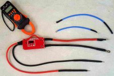
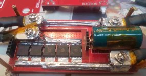
For those who like pics, the loop at the top is a shunt to allow my £18 Holdpeak clamp meter https://www.ebay.co.uk/itm/Digital-Clamp-Meter-Multimeter-Handheld-RMS-AC-DC-Mini-Frequency-60M-Ohm-Temp/153507698586?hash=item23bdc5979a:g:gF0AAOSwDXldyoAm to measure 1mS blips up to 1800A (agrees with static resistance mesurements and scope values). The lower image is some soldering to be proud of lol, but it works. I started, thinking the bigger crimps would be good enough, but any movement on the now thicker wires moved the crimp conector and increased the resistance on the undersized bolted joint, so rather than soldering the cable direct to the PCB or adding a better PCB connector; I stuck a blob of solder on each to resist rotation. To be improved at some point if I need to (easy to move). My resistance optimisation method was to put 1A constant current through all circuitry, probe at 10 micro volt resolution and add copper where needed. 10 AWG cables (5mm2) were changed to 8 on the probes and 5AWG on the supply, connections checked and improved where needed, crimps soldered, probes soldered etc.
Seems a cheap, simple upgrade for those on a budget. Could be done with a couple of bits of wire and a soldering iron.
Interested to know from the experts what I've missed? More data available if of interest.
Might hook up another battery (or 4) and see what it does at 1500A +

Edit - tested up to 1600A - no problems and no inductive spikes above 25V on the scope - ask if you're interested.
Expecting that the next upgrades will be copper nails in place of 1mm dia probe pins, a TVS accross the supply in parallel to the capacitor and a freewheeling diode on the probe side of the circuit to deal with the extra inductance.
For those considering / needing higher currents; the power pcb should stack with another, just extend the headers and parallel power and add bigger busbars than I did
The driver chip is on the control board and you may want one per bank of 6 FETs so I was vaguely considering piggybacking a second on the first if you're happy soldering surface mount chips (just fiddly - ok with patience if you can solder)
There's a cap accross the supply for smoothing and some diodes going from the -ve to the FET gate which I wasn't sure about function
300 ohm resistors to the gate probably keep the FETS switching together.
The controller allows timing from 1 to 99 mS and displays voltage and this setting. There is an auto function that detects reduced voltage acrosss the probes and welds after a bleep or a manual switched input
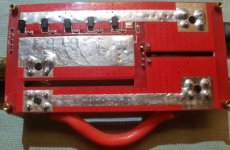
Image shows larger cables, 5AWG and 8AWG in place of 10 AWG plus more copper and solder on PCB.