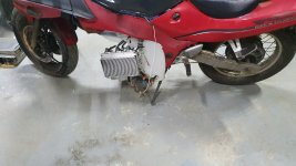
Suzuki RF400E, now with Enertrac MHM602

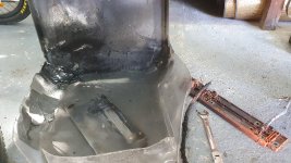
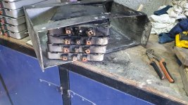
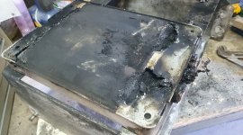
Thermal event!
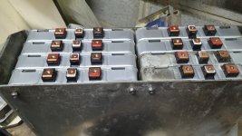
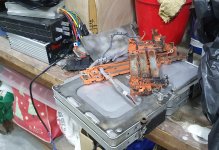
So, due to stupidly ignoring a lower voltage readout on a cell and a combination of overconfidence and long term moisture damage I got once of the cells to reverse or internally short during operation (120km/h speed test with new controller, see Lebowski thread), destroying a module. I had previously attributed the lower readout to a wonky connection from the balance lead, big mistake.
No thermal runway, the remaining modules are fine as far as I can tell. The AESC modules are quite safe luckily.
The only damage was to the plexiglass cover and the aluminium bar (660°C melting point!) where it vented plus some soot.
I just got the bike back together as I also moved the fuse box and changed for a shielded cable on the primary positive connection.
Down to 34S, but in time for the meetup tomorrow: DIY Electric Vehicle Meetup – Tog Hackerspace

Keep in mind the modules are 12 years old by now and most have been outside on the bike with little protection since the 80100 experiments and then used daily since 2017. Seal your battery boxes, guys!
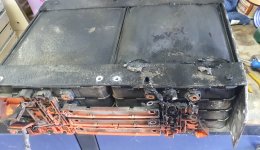
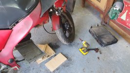
20230729_100903.jpg20230729_100913.jpg20230729_100919.jpg20230729_102741.jpg20230729_102907.jpg20230730_161244.jpg20230730_161251.jpg20230730_161256.jpg
 
Are you using field weakening now? Do you have a higher maximum speed with the Lebowski compared to the Kelly? I see from the config data you posted in the other thread that you have menu h) sub item b) set at default settings for sensored operation. As discussed increasing b) towards the default sensorless value seems to help with the transition to full FOC mode. Arber has found the same with his Lebowski/Leaf powered car so it is worth trying. If you still have a rough transition between drive mode 2--> 3 you should increase menu d) sub item f) at 500 erpm at a time and see if that helps.

The other thing that may need attention is the regen potentiometer, iirc you said you had not fitted one. If that is the case you should tie the regen input to ground, you do not want to be presenting electrical noise on the inputs that are connected to the ADC circuitry inside the DSPIC.
 
Cheers, appreciate your feedback!
No field weakening yet and yes 120km/h iswas possible with 36S and frying one module :p

This is the setting change for H\b in case someone isn't following:
Code:
a) autocomplete

b) dr2: speed filter 50% step response time: 43.2 msec
c) dr2, dr23: error current 50% step response time: 17.1 msec
d) dr3: error current 50% step response time: 4.28 msec
e) battery voltage filtering time constant: 0.08 sec
f) acceleration filter time constant: 171.39 msec

z) return to main menu

------> a

a) autocomplete

b) dr2: speed filter 50% step response time: 212.5 msec
c) dr2, dr23: error current 50% step response time: 20.1 msec
d) dr3: error current 50% step response time: 5.00 msec
e) battery voltage filtering time constant: 0.10 sec
f) acceleration filter time constant: 200.87 msec

z) return to main menu

D\f is
f) erpm dr2 jump to dr3:

------> z

My problem is that drive_2 operation is still not satisfactory, so extending that theshold will make the bike less usable day-to-day until tackled. Appreciate the shout about the throttle_2.

To do:
0) ground throttle 2 (done, no difference)
1) add shielding mesh for Hall sensor wiring. I might even shorten it as it was extended by the original owner and I don't need the additional length any more with the Lebowski controller. (Done, maybe some minor improvement? have also done the phase wires like Eric did, need to ground it to enclosure still)
2) check halls signals / calibration before & after
3) add the 3-step regen switching I've been contemplating, connect rear brake switch to 2nd relay to enable regen
4) adjust H\b
5) increase D\f if needed
6) increase phase amps
7) install 350A contactor, move fuse, create HVJB
8) increase battery amps
 
Last edited:
My problem is that drive_2 operation is still not satisfactory, so extending that theshold will make the bike less usable day-to-day until tackled. Appreciate the shout about the throttle_2.
It is difficult to determine if the issue you have is entirely down to sensored drive mode 2 or transition mode 23 when you have the transition set at a low erpm. If you set the drive 2-->3 transition at say 7-8000 erpm you should be able to get a better feel for where the problem is. It is an experiment, not a recommendation for ongoing use. Once you have determined where the issue is you can concentrate your efforts there. A number of people have found that you get a superior transition from sensored to full sensorless FOC mode at higher erpm's. That said, it should always be your aim to get into sensorless FOC mode at the lowest erpm that you can.

What was your previous top speed with the Kelly controller? field weakening will give you a further boost for sure.
The battery fire sure looks crispy, glad you didn't get injured or incinerate the bike.
 
What I found with Hall sensors is that they can be unreliable, kinda. If they are really in the motor then they will pick up the field from the permanent (rotor) magnets PLUS the field from the coils. At high current the sum of those two represents a phase shift that can make transition rough. The higher the phase current, the stronger the field from the coils, the worse the effect is.
If the hall sensors do not see the coil induced magnets field the situation is much better. Also a separate resolver outside of the actual motor does not suffer from this effect.
Another thing that I noticed is that the output signals from hall sensors are not nice square waves. Especially when they also see the field from the coils you get very rough looking signals, even more so at high phase currents. For this reason the schematics include a RC filter in the output lines of the hall sensors. Increasing the R or C might help clean up the signals, but too high RC will cause a phase error at higher rpm.
 
Also at high currents if the hall wires run parallel to the phases from motor to controller, in the same cable, signals can suffer from induced currents.

If a low-latency buffer was made between the MCU and the signals, you could use an arbitrarily high pullup voltage at the buffer input for a much better signal to noise ratio, and the buffer can then output a logic-level signal for the MCU.
 
I had a kelly controller on a HSG motor, and the kelly heated up the HSG (IPM motor) FAST. I was running 160V. The power was OK, but hit a brick wall because the HSG wanted 300+V to spin up, and the kelly had no feild weakening or anything. The kelly's are great for getting you going, but over all just crap. I switched over to an IMA inverter with lebowski brain that KiwiFait built for me, and the difference was NIGHT AND DAY!. Lebowski was hard to set up and get right, but OMG when it was right it was RIGHT!! FW was AMAZING. When the FW was at 0 amps the lebowski was 25% better than the kelly. (ass dyno numbers). the motor still hit a brick wall at about 5200 RPM. But with FW... it was AMAZING... you could feel the FW come on and just keep pushing you back.... I can not say enough good things about the lebowski controller and Kiwifait's help!!!
 
I had a kelly controller on a HSG motor, and the kelly heated up the HSG (IPM motor) FAST. I was running 160V. The power was OK, but hit a brick wall because the HSG wanted 300+V to spin up, and the kelly had no feild weakening or anything. The kelly's are great for getting you going, but over all just crap. I switched over to an IMA inverter with lebowski brain that KiwiFait built for me, and the difference was NIGHT AND DAY!. Lebowski was hard to set up and get right, but OMG when it was right it was RIGHT!! FW was AMAZING. When the FW was at 0 amps the lebowski was 25% better than the kelly. (ass dyno numbers). the motor still hit a brick wall at about 5200 RPM. But with FW... it was AMAZING... you could feel the FW come on and just keep pushing you back.... I can not say enough good things about the lebowski controller and Kiwifait's help!!!
I'm with you, however I only have Hall sensors while you had a resolver and some gearing advantage :)
 
Had some time for tuning last night and worked on the settings after the shielding and then re-running Hall calibration:
4) adjust H\b
5) increase D\f if needed
6) increase phase amps
So I raised D\f (erpm dr2 jump to dr3) to 8000 and had a smooth transition immediately, then still at 4000.
No more jumpiness, maybe a small improvement in accelleration, I did notice a quicker rise in heatsink temperature though.
I think the latter is due to the prolonged stay in sensored mode and my sensors are a bit off:
beforemod 60
code: 0, angle: 358 deg, confidence: 0, used: no358
code: 1, angle: 81 deg, confidence: 6, used: yes81-27723
code: 2, angle: 202 deg, confidence: 6, used: yes2021211
code: 3, angle: 149 deg, confidence: 6, used: yes149-537
code: 4, angle: 329 deg, confidence: 6, used: yes3291800
code: 5, angle: 22 deg, confidence: 6, used: yes22-30753
code: 6, angle: 261 deg, confidence: 7, used: yes26123959
code: 7, angle: 358 deg, confidence: 0, used: no3589737

Funny enough it stopped saving Hall stats ( I might get one or two counts), so I can only play with the offset manually.
Left the Halls alone and increased H\b (dr2: speed filter 50% step response time) from 50 to 75ms, and tested again, not much difference.
Lastly I dropped D\f to 2000, still all good and then raised battery amps from 150 to 155 and phase from 190 to 195 as an "attaboy" for myself. Extended test drive was fine and I got to work today OK.
Edit: 210A phase is good, but the transition is a little rougher, so I will push H\b higher next. Done, 125ms, which is still Ok-ish at 230A but needs adjusting.

Overview of each config set:
erpm dr2 jump to dr3 (D\f)dr2: speed filter 50% step response time (H\b) [ms]Battery/Phase Amps [A]Result
800050150/190smooth transition, some heat
400050150/190smooth transition, some heat
400075150/190smooth transition, less heat
200075150/190good transition, less heat
200075155/195good transition, less heat
200075155/210OK transition, but noticably struggling
2000125155/210good transition, slight hesitation to sync
2000125155/230lost sync on one occasion hot off the charger, manageable
2000175155/230good transition, very slight hesitation to sync
2000175155/250lost sync on one occasion, manageable
2000225155/250good transition, but being able to WOT leads to conking out in Drive_2 (Hall only)
2000225155/250Increased error current thresholds & started adjusting Hall offset, see post #138
 
Last edited:
Overall that is a good outcome, I would be interested to see how 40-50A of field weakening affected your top speed.
Funny enough it stopped saving Hall stats ( I might get one or two counts), so I can only play with the offset manually.
Left the Halls alone and increased H\b (dr2: speed filter 50% step response time) from 50 to 75ms, and tested again, not much difference.
That is odd, haven't come across that situation before. Are you sure you have "online parameter save" set in menu Z?

I don't understand your HALL table columns "before" and "Mod 60". A BLDC motor with 120 degree HALL sensors spits out 6 unique three bit Gray codes, one for each 60 degrees of electrical rotation. So what you need to look for in the data the Lebowski controller displays in menu l) is the difference in angles between the six codes bearing in mind that the codes are not sequential as in 1,2,3,4,5,6.

In your case you have: 81-22 = 59 degrees good
149-81 = 68 degrees not so good
202-149 = 53 degrees not so good
261 -202 = 59 degrees good
329 - 262 = 67 degrees not so good
360 - 329 + 22 = 53 degrees not so good
Typically I don't see any more than +-4 degrees with HALL sensors. You could probably reduce the mean deviation with the offset feature in the HALL menu l) sub menu g) and h). Obviously the prerequisite being that you can track down and resolve the online data saving issue you have. The angular errors in the HALL data is another good reason to get the transition into full FOC drive mode 3 as low as possible because that is when the phase current waveform is in phase with the BEMF and power conversion from electrical power to mechanical power is maximized.
 
As per updated Post #135, transition is good now but have to deal with conking out in Drive_2 (Hall only) again.
I set error current thresholds to autocompleted based on 300 phase amps, which changes the following values
B\g 80->90
B\i 62.5->75
B\j 31-> 37.5
then dropped phase amps back to 250. Unfortunately this didn't make a difference.
Tried again based on 350 phase amps, i.e. 105 / 87.5 / 43.5, again no difference.

I'm also wary of increasing them too much after reading Lebowski's motor controller IC, schematic & setup, new v2.A1, though that's based off a much older version and a sensorless start I believe. Happy to be educated about error currents in the Lebowski world...

I'm now focussing on the Hall offset again:
Log#L\g (forward Hall offset)Hall statistics
41+2.5 forward
count: 76
average: -2.77 deg
std-dev: 3.93 deg
changed to +1
43+1.0 forward
count: 18
average: -2.03 deg
std-dev: 4.14 deg
changed to 0
440 forward
count: 31
average: -1.13 deg
std-dev: 4.75 deg
changed to -1

I think it's getting rougher and the deviation keeps increasing but the sample size is too small so I might increase D\f again to collect more samples, maybe on 230 phase amps to contain the heat buildup. (does anybody know what the heatsink temperature for the IMA might be?)
 
The error current setting needs to be within the range of accuracy of the sensors used. The current sensors in the IMA inverter are rated for 300A after that the linearity is not guaranteed. You could probably push the current sensor output amplitude to +- 2.25V which would give you ~335A. I wouldn't go past that. I think it would be worthwhile to revisit the inductance menu.I recall you increased the phase resistance significantly and although the latest Lebowski firmware version is less impacted by phase resistance the closer it is to reality the better performance you will get from the inverter.

You could also try enabling the acceleration limiter, it has been known to solve conkouts due to jittery sensor data which may be applicable to your situation.

How does acceleration and top speed compare to the Kelly controller?
Happy New Year Roger and Bas!
Sorry for the lack of reply, the bike has been performing adequately enough (backed off to 250A phase) that my focus shifted.
- acc limiter didn't make a difference unfortunately
- acceleration is good once in drive_3, top speed is improved (not backing off over 90km/h), but untested, see thermal event... Certainly feels like I could break speed limits on the motorway at 34S
- I have pushed phase resistance from 100 to 110 and had to back off at 120 as it was running "rough". Not sure how that might influence other parameter's effects.

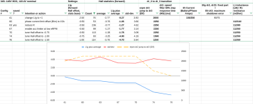
As it's quite cold and I can't "mess up" the bike's config too much I went through my logs and tried to put the last changes (including mistakes like changing multiple things at once) in a Google spreadsheet (you can comment) to make some sense of it.

Another odd thing is that I had knocked the hall power connector off with some package (hindsight) and re-ran the config to find out what stopped the bike all of a sudden. Since then it randomly "kicks" (pushes forward slightly) a tiny bit on startup or reset.
I was looking to send a "working" config on but wanted to get to roughly the same state again, thus the tracker above as the lates one is 16 changes ago...
 
What settings did you use on the acceleration limiter? You should be setting the kerpm/s to a realistic maximum acceleration rate that your bike could achieve. So estimate how fast you think you can accelerate to say 40mph in dry conditions, calculate back to the erpm the motor is running at 40mph taking into account the number of pole pairs your motor has. Then divide that by your acceleration time. That will yield a number that will function correctly if you experience wheel spin in poor traction conditions like snow, ice, or crazy airborne activity.

From your spreadsheet I see you have been playing with menu B\m. Using that feature is now discouraged and the recommended strategy is to reset current sensor offsets to zero and leave them there.

The spreadsheets suggests you are getting a smooth transition to FOC mode with the transition set at 4000erpm. If that is the case I suggest you set it at 4000 until such time as you resolve the HALL sensor misalignment. At the end of the day if it works well at 4000 that is a win.

I may be wrong but I have a theory that the rough transition from HALL sensored mode to sensorless FOC is caused by a misalignment between the rotor angle information from the HALL sensors being distorted by phase currents and the angle reported by the Lebowski sensorless algorithm. Since the Lebowski is the Max Verstappen of sensorless FOC motor control algorithms it is still worthwhile endeavoring to get the transition as low as possible without comprimising driveability.

With regard to the motor phase resistance changes my previous comment was intended to suggest lowering it rather than increasing it. I have come to the conclusion that it is best to have it as close to the motors actual phase resistance as is compatable with smooth running. One thing I did discover is that if you set the phase resistance way too high it can cause the field weakening algorithm to lose throttle control which can lead to a potentially power stage destroying decision to cut the contactor.

Interesting about the kick on startup or reset. I only see that happen when I have manually set an incompatable loop sample frequency in PWM parameters menu A/h. Is it possible the connector was damaged when you hit it? May pay to check that none of the wire crimps have been loosened.
 
Cheers Roger, insightful as always.

I'll have a look at the acceleration limiter (AL) again, and adjust G\h to cover Drive_2 instead - it defaulted to 10 & 12 k-erpm, which is way beyond my normal speeds. I'm actually close to ~10km/h for every k-erpm...

Got it, B\m will go back to zero, I was wondering why I had values under F
Code:
b) perform offset measurement
   sensor a: -117.5 mV
   sensor b: -125.0 mV
   sensor c: -135.0 mV
(Zeroed out in config #61)

The transition is actually OK at 2250 with 250A phase, which I intend to increase once I'm sure I can rely on the setup in Drive_2 (sensored) with the above.

Sorry for the misunderstanding, L is at 112 and R is now back down to 80. FOC feels a little less "harsh" with that.
From our initial session we had the following measurements:

Code:
b) FOC measurement current: 149.9 A
c) FOC measurement erpm: 9.99 k-erpm
d) perform impedance measurement

L) inductance: 119.68 uH
R) resistance: 36.87 mOhm

So (more for myself) next iterations are:
- B\m to zero
- iterate R down towards 40 in steps
- re-try the AL, maybe .5 to 2 k-erpm

I got some decent Hall stats in #63, do I aim for a low difference on the offset (average) or rather minimize the standard deviation?

Code:
 forward
count: 236
average: -0.77 deg
std-dev: 4.62 deg
 
I got some decent Hall stats in #63, do I aim for a low difference on the offset (average) or rather minimize the standard deviation?

Code:
 forward
count: 236
average: -0.77 deg
std-dev: 4.62 deg
Looks like you are making good progress.

If you can reduce the average HALL offset error then the Std_dev will also drop so aim to get the average offset as close to zero as you can. Don't forget to zero the collected stats every time you make changes to the HALL forward offset and once you are happy with the HALL settings turn off the online parameter save setting in menu Z. Bear in mind that the magnitude of the HALL error stats are dependant on the phase current requested by the throttle position when you are riding the bike. That being the case, it is likely best to ride the bike in the exact manner you would in daily use so as to not skew the data points when you are collecting new statistics.

Definitely turn off B sub m and reset the current sensor offsets in menu F. Lebowski explained the reasoning behind this in one of ARLO1's epic threads iirc.
 
Thanks Roger!
Hall sensor data still needs to be collected/accumulated over multiple rides to have a somewhat reasonable sample size. This is offset by the desire to have a usable bike as it's used daily.
More steady progress in the meantime:
  • B\m turned off and sensors reset in #64 straight away
  • kept reducing R to 50, feels a little smoother and less "grunty"
  • tried the acceleration limiter at low eRPM values without success - the bike wouldn't even move
  • Day to day I'm carefully tuning erpm dr2 jump to dr3 (D\f) and the Hall offset, they are now at 1100 (~12km/h or so) and -1.5
Looking at the stats a bit and taking any count of 50 or more, I think there is a relationship between the measurements and D\f. Could it be that the lower D\f is, the more negative the "average" plus L\g, i.e. the desired or calculated offset becomes? Maybe there is less (Hall)disruptive EMF at low RPMs?
Filtered and plotted:
1709895685804.png
 
Looking at the stats a bit and taking any count of 50 or more, I think there is a relationship between the measurements and D\f. Could it be that the lower D\f is, the more negative the "average" plus L\g, i.e. the desired or calculated offset becomes? Maybe there is less (Hall)disruptive EMF at low RPMs?
Filtered and plotted:

It is the absolute magnitude of the error that matters, not the sign. Given sinusoidal waveforms for the bemf and the current being driven into the motor, the power lost due to a 4 degree misalignment will be more or less identical regardless of the sign of the error.

Your data shows that the absolute value of the error is increasing with a lower transition point which suggests to me there is more disruptive EMI at lower erpm not less ie lower erpm transitions = more error. That certainly ties in with my theory as to why a higher erpm FOC transition point results in a smoother transition.

When you have say an offset of -1 degree set and your stats show you are still getting -3.7 degrees of error that is telling you that your next try should be -4.7. Sometimes that helps, sometimes not. Certainly there is a degree of variability due to the fact that it is impossible to recreate the exact test conditions every time you make a change.

I would be prioritizing a smooth transition over the HALL stats, that is to say if it feels right on the road then it is right!
 
Back
Top