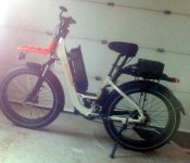
Terrain Control alternate to PAS/Torque control

On speed control, It appears that it can be achieved using the cycle analyst alone.
Throttle mode can be changed to "speed" and the autocruise function need setup,
after that it looks like the CA will control the bike speed when autocruise is activated.
Maybe one of the CA gurus can confirm.

This got thinking that the inclinometer signal could be sent directly to the CA and
used to control the power output; eliminating the need for the Arduino.

Rather than come in through the throttle, maybe inputting the inclinometer
signal to the Aux Analog may be the way to go; leaving throttle operation unaffected.

The CA looks like it maybe was setup to do this type of experimental operation;
if so, what an amazing device!

The roads turned to slush yesterday and refroze but the plow caught it before the freeze.
The new snow fell and now the fat tires are noiseless and there's just a slight whirrrr of the motor.
Short ride and a bit treacherous on the curves but still a good one.

So I have a new set of data. I t had to discard the previous set because I had parsed out the GPS sentence
but the Grin Trip analyzer is looking for a complete NMEA sentence.

Donn, thanks for your input. Inclinometer with speed trim could well be the solution for stable control
since the signals are so noisy. Sorry it took me 18 more posts to "see the light"...
 
I collected a couple sets of data and let it rest for the night.

Yesterday morning the data collection was stalled from the Arduino to the Pi.
Working on it all day yesterday, I tried everything. It improved a bit but
never came back 100% so I tried everything again. still ran in fits and jerks.

Since I had all the other data flowing directly to the Pi, I decided to wire the
sensors to the Pi and take the Arduino out of the loop.
Twice now it has been the source of problems so out it came.

Attempting a very reliable platform, I simplified the wiring;
taking the throttle input 'green' wire directly to the CA

I decided I really don't like messing with the throttle directly; too many things
can go wrong; better to leave it in the hands of experts :)

So now the Raspberry Pii will read all the data directly, calculate a Terrain power and output
to the CA. period.

My new philosophy is that for a mobile platform, the KISS principal applies.
 
So the Arduino is gone and everything is wired directly to the Raspberry Pi.
It's a 4b and although the size of a deck of cards, it has 8gb Ram, TWO hdmi and four usb ports;
basically a little board with interface connectors sticking out all over it.
(And that awesome 7" touchscreen for mobile apps)

It is now reading the GPS and CycleAnalyst serial streams and the inclinometer signal.

The arduino was showing a "nan" when I tried to calculate the inclination rigourously..
It's just so difficult to debug the Arduino while the pi has a full blown debugging system "Visual Studio Code."

After debugging the long inclination expression: BINGO!
The signal noise is way lower and looking really stable.
I was looking at each x,y,z axis as a separate signal but when combined together in the calc
it seems one axis cancels out some noise on the other axes.

Bike is ready, waiting on the weather....
 
The terrain control was working so good (in the garage :) that I decided to move to prototype #2: Stealth Mode
I was getting WAY too many second looks in my small farming community so decided that a stealthier design was going to be important for the next riding season.

The new project box is 3" x 8" (stock-controller size) while the old was 10" x 10" (satellite tv rooftop box size);
a 75% decrease in size! Obviously, some items had to go: fFirst off was the touchscreen and the CA was moved to its grin mount.

With no displays on the box, the front rack could be flipped right-side up which is definitely less conspicuous :)
The inclinometer is in it's own enclosure so it can be poistioned away from any ferrous metal or magnetic fields.
It tucked nicely under the rack and is barely noticeable.

Prototype #2 is almost completed. I'm waiting on a tophat for the pi that provides n DAC for analog outputs; which is not supported by the pi or the arduino out-of-the-box. The throttle output to the CA needs to be a signal from 0.85v to 3.5v. I tried a PWM output both from the pi and arduino but the CA display was showing a lot of flickering on the throttle input; something which didn't bode well. The analog output should provide a steady signal.

Speaking of flickering signals, it took a lot of attempts to smooth out the accelerometer signal.
Having tried several examples for the pi with poor results, I resorted back to the arduino and after several more attempts found some sample code that produced a rock steady signal and didn't whig out when crossing the 0 degree inflection point.
(It includes a software low-pass filter which works great (something afzal suggested on day one).

Squeezing a pi, arduino, relay, GPS and 5v power supply into the new box was no small feat and I had to use a two-story design inside to make it work. (I'll post a photo after I get the pi hat installed.)

more later...
 
OK, an Arduino Nano BLE has arrived and it's a game-changer!

It's is a low powered, bluetooth enabled board with a built-in 9-axis IMU and programs in python;
or in terms of Terrain Control, a wireless inclinometer that can run off a lithium battery in a tiny package.
The Holy Grail!

No power required (except for charging the battery).
No comm cable required.

In the simplest form, just it needs just a couple of buttons for power and Terrain Mode On/Off, an LED to show Terrain Control is active and a throttle output to the CA or ebike controller; all in a package the size of a deck of cards with wireless comm for data logging.

The design is taking a major revision to the nano scale :)
 
So the stealth mode version is now garage complete.
It looks a lot better with the project box on the rear rack; although the box didn't get any smaller :)

The NANO version is coming along nicely as I have it running on battery power with the IMU reporting nicely.
The effort now is to get the low powered bluetooth link between the pi and the Nano.

The project box is an aliexpress plastic bike controller box; not exactly NANO size but a lot smaller than the 8x8x4 "stealth box".

The NANO is powered by two 2.5ah LiPos running in parallel. LiPos and NANOs are not a perfect match as the LiPo's voltage will fall below the NANO native 3.3v lower limit at low charge and is too high at full charge. So I used a Sparksfun LiPo charger/booster that output at 5v through it's booster function; fed to the incoming regulator on the NANO; (5-18v).

This setup works but is not very battery efficient as it involves a booster which are less efficient than buck converters and the route through the Arduino regulator which is notoriously inefficient. For now, I'll test with the existing setup but to minimize power draw a new one is on the drawing board.

I struggled with a more efficient power supply; the first question being the battery voltage level. For supplying 3.3v directly to the NANO pads, it takes two LiPos (7.4v) for reasons stated above). At first 7.4v seemed pretty hokey but the more i thought about it...

7.4v packs are readily available as they are used in RC projects. 7.4v is a good range for using 12v chargers, battery and solar. At full discharge they are still above the 3.3v Nano minimum so every microwatt is utilized; of course there is some inefficiency in the 7.4v to 3.3v dc converter but I've ordered the aliexpress best :)

So far, the Nano33BLE is looking to be a good platform for mobile (battery powered) projects.
Here's a photo comparison with the nano sitting on top of the "stealth" box:

ATTACH]
 
Several days of attempts to get a bluetooth low energy link between the Pi and the Nano33 finally resulted in success (after many failed attempts) at midnight last night!

The serial monitor lit up a little and then this flow of data rippled down the screen.
comm links can be a real pain and BLE is no exception but when the spice starts flowing, all is good.

I had to try many examples on both the python side and the nano side; trying every library and script I could find.
And then there was this post in the middle of a very long thread that had simple, easy to understand complete arduino code that read the accelerometer, calculated the euclids(yaw, pitch and roll) and used a Madgwick filter (not sure what those are but everyone thought they were the cat's eye :).

Then the last subroutine sent the data over the BLE link. Brilliant. A couple posts further said the code was bunk so I shelved it until when completely desperate last night,I uploaded to the Nano where it compiled without a whimper and uploaded perfectly.

The code get everything ready and then it starts advertising and looking for something to connect to, with the serial monitor blank.

An 8-line script on the python side looked for peripherals, found the nano,connected and the nano started spewing something that looked like hyroglyphics on the pi side. Every decoding effort failed. Then on the same thread from above, some guy injects a 4-line reply with one line of python code that unlocks the stream. The line is a call to 'struct' which is a C language class that, get this, converts from C-compiler compliant bytes to python interpreter compliant bytes.When the struct command was run against the data coming from the Nano, the glyphs materialized into three signed floating point numbers being sent from the Nano. Hurrah!

Now I just have to get the Nano to accept some data from the Pi.....bi-directional comm....

roll, pith and yaw data - very fast.
 
Four days later, the nano design is still reporting over bluetooth to the Raspberry P;i using two LiPos.
I'm just going to let it keep going until it blacks out, then put in some power conserving software measures and test it again but it's really looking good so far!

The Pi is reading and writing to the nano at 1 HZ and never drops a packet.
I tried connecting to it using Win10 and that's a different story.
Windows just doesn't want me to connect to a device not on their 'list'.
They removed the bluetooth assemblies from Windows.core and recently published some examples
that discover the nano but won't connect. It looks to me like Microsoft doesn't want us connecting
to custom bluetooth devices. Go figure.

I had to revisit the stealth design because the lid wouldn't go on :)
It was a good opportunity to put some additional hardening on the connections to ensure potholes don't cause any sensor disconnects...

The techniques I learned from the nano version really helped the stealth version:

There are shields or tophats available for both arduino and pi that provide a solderable breadboard and screw connections. I started soldering male headers onto the 'hats' to create multiple connections for power, ground and the I2C connections (SDA/SCL). Any wiring from the outside the box I tried to land on screw terminals. Everything is much more robust now and small enough I can get the top on!

Sure looks stealthier and I'll document the final design:

The box has a pi 4B with 8gb RAM communicating over USB to a arduino mega 2560 and a cycle analyst_ v3.
The pi receives GPS data from a Neo6M using UART and communicates with a nano33 over bluetooth low energy.
The arduino is reading a LSM303 accelerometer and BMP388 temp/baro pressure sensors, using I2C.
The arduino also reads the multi-fuction switch button/up/down and outputs a throttle signal to the cycle analyst.

All is powered by a druk 12v-5v converter (3a possible but runs best below 2a without cooling).
The cycle analyst shows a steady 6W draw from the stealth box, so just over 1a at 5v.

12v is supplied to the box from a 100w 48v/12v converter.
The power system is very stable and runs a long time on the 52v 20Ah LiIon ebike battery :)

Stealth Terrain.jpg
 
Well, all goes well, untl it doesn't.
Seemed just like any other day but everything started going wrong.
The nano battery ran out in 50 hours with no power saving techniques. No problem.
When I went to charge it, the Sparkfun lipo charger quit working;
this is the second one that's died. I hooked up the nano with usb to the pi until
I could get another charger.

So I went to do a small task on the Raspberry and at startup, the SD
card failed, dead. I have never had this happen before and it took a while to sort out.

I had an almost identical build on another card, so I put it in and everything looked good;
except bluetooth wasn't working. After a couple hours of sudo this and sudo that,
I gave up and started from scratch with a new image.

As I built-up the image for the Incline Control, I caught the step that disabled the bluetooth.
Imagine, an instruction.com "how-to" by a random internet guy messed up the bluetooth.
The instruction was modifying the boot files for using a serial GPS so I bypassed
that step and installed the GPS module on the Arduino. After a couple days of reprogramming
the Arduino and python programs are working together smoothly again.
 
I had two issues with the way the Terrain Control was running;
one was the outdated CA multi-function switch I bought which although it worked was very sluggish.

I looked for a replacement online but really couldn't find what I wanted, when I remembered there was an old RAD controller that I had outgrown and it had the Mode/Up/Down switch i needed. So I cut the cable to it and found 4 wires. After experimenting with it a while I found it was one for each switch plus a common wire. Yipee!

I put 5v on the common wire and checked the switches but the ones and zeros were bouncing around randomly; the wire leading back to the arduino was 'floating' when the switch was not being pushed. I tried a 1megohm resister on each input to ground and it helped for a bit but then the random glitch again. Finding one of the resistors leads had broken, I made another bundle of three, hooked them up and all was good for a few switches and then random noise.

It took me far too long to realize that 1megaohm was too little resistance and the current of 5ma through the resistor was melting the resistor leads. When I upped the resistors to 10megaohms, the switch worked perfectly with very quick response.

The second problem was the PWM output to the arduino for the CA throttle input. It was noisy as well, not as random but still noisy. I just solved that issue today with a MCP4725, a digital to analog converter targeted at the audio business.

I thought an audio IC would be a good one but wasn't sure. When I entered the device address from the documentation, it would not respond. An I2C scan gave me the address of everything on the bus and by process of elimination I figured out its address was 60 not 62 or 63 as stated; means it's a counterfeit IC but hey, it did come from alibaba :)

With the DAC inline on the throttle to the cycle analyst, the CA throttle input is rock steady.

Warmer days are coming so I should be able to get out on the road for testing soon...
 
HillCruiser said:
I put 5v on the common wire and checked the switches but the ones and zeros were bouncing around randomly; the wire leading back to the arduino was 'floating' when the switch was not being pushed. I tried a 1megohm resister on each input to ground and it helped for a bit but then the random glitch again. Finding one of the resistors leads had broken, I made another bundle of three, hooked them up and all was good for a few switches and then random noise.

It took me far too long to realize that 1megaohm was too little resistance and the current of 5ma through the resistor was melting the resistor leads. When I upped the resistors to 10megaohms, the switch worked perfectly with very quick response.

This is very strange. :? There is no way I can imagine that 5mA could melt the (typically tinned steel) leads of even a tiny 1/8w resistor, even if they were made of solder. That's only 0.025w.

And anything that melted resistor leads should melt all the series wiring leading to and from the resistor, and the plastic of the switches and even the plastic casing of the mounting/housing for the switches.

If you are using 5v thru a 1megohm (1000000ohm, brown black green) resistor, you won't even get 5mA, anyway--you'd only get 5microamp (5uA).

A 1kohm (1000ohm, brown black red) resistor at 5v would give 5mA, but again, it won't melt the leads.

A 1milliohm resistor at 5v would give 50A, and *that* would melt stuff. (250w) ;)

a 1ohm (brown black gold) resistor at 5v woudl give 5A, and if it's not a heatsinked resistor it would get pretty frickin' hot (25W). :lol:
 
HillCruiser said:
I put 5v on the common wire and checked the switches but the ones and zeros were bouncing around randomly; the wire leading back to the arduino was 'floating' when the switch was not being pushed.

Would be far easier to use the internal pull ups in the Arduino and switch low. Also you probably need a denounce, which can be done in software.
 
thanks for all the analysis and suggestions.
I don't know what to think about the resistor leads failing;
it happened twice right at the solder joints so maybe that was a factor as I do tend to overheat my joints sometimes.
(There's a little bit more that was happening...On my third try I was hard-pressed to find the right size resistors when a package arrived from aliexpress with a beautiful resistor kit. For the last attempt, I used the well-marked resistors from the kit.)

I did try the internal pullups but always got zeros whether the switch was closed or open, that's when I went to the external resistors. Anyway, I have seem to have a correct size resistor on now and after many checks, it still works flawless.

With the stealth version wrapped up I went back to the nano version. A couple of nanno33 IOT's showed up so I begin checking them out. Tiny little boards but Ithey have both low energy bluetooth AND wifi so I tried both options and both worked good. For the wifi, I couldn't find a TCP example but there was a UDP sketch so I loaded that, setup a UDP connection client on the Pi and after many frustrating hours I finally figured out how UDP packets are coded and decode and suddenly they started talking to each other. Rock steady comm but I am only a few feet away :)

The IOT also has a built-in IMU but a different part number than the nano BLE so the code needed a couple of tweaks but was soon reporting Pitch, Roll and Yaw to the Pi. The pitch variable is the one of interest because it shows the bike's inclination. It is working well, giving good response and low noise.

Another great thing about the IOT is that it has a built in DAC; only one analog output but I only need one for the throttle signal to the CA. For the stealth version I had used an external DAC IC but that shouldn't be needed for the nano version.

My python program on the pi was starting to show some lagging under load; the Ui would slow down gradually over time and the memory use was rising continuously so I went back into it deep to figure out what was happening. There was a LOT of spaghetti code back from my early days of learning python so I did a 3-day super duper overhaul on it. The pyqtgraph objecst weren't releasing and doing garbage collection on the non-global objects. Turns out its a common problem so I went against everything I have ever coded and started introducing many global variables. After this it started up with a smidgen more memory usage but it didn't keep rising and the one second updates are crisp; every second it reads the arduino mega, arduino nano and cycle analyst data streams, updates all the time variables from the GPS, plots the graphs, etc. etc. There were many area of very, very poorly written code that needed completely redoing (and I used to be so proud of that code:)

There's a lot going on but the pi 4B with 8gb of ram can slice through it all nicely as long as it has some efficient code to run.
I still have a couple of the major loops to rework and have them bypassed but the memory usage is now at less than half a gig and the 4 processors are all running 15% or less! Drastic improvement for the way it ran before.
 
Received a new 2s6p lipo battery pack and decided to try it out on the nano for an extended run.
Voltage checks showed about 0.1v decline every day, which is WAY too much.

At first glance I saw 4 LED's lit; the switch on the battery, on the power supply, the switch to the nano and one power light on the nano . The switches were easy, just disconnected the common wires. The nano power light can be turned off in the sketch which left only the power supply light.

I had just received some new 3.3v power supplies(without LED's) from aliexpress, so decided to go with powering the nano directly, bypassing the onboard regulator (the regulator is legendary for using a lot of power.) You just have to flip the board upside down and use an exacto knife to sever a small solder bridge between the two 3.3v solder pads. You then run the 3.3v from the power supply to the 3.3v and GND pins on the nano.

Once finished, I powered back up but without LED's it difficult to see if the nano is running:)
So I pushed the reset on the nano and after reest, the power light comes on for a nano second and then goes back off; showing the board is powered and the sketch is running again.

I'm still checking but it looks like the power draw dropped to 1/4 of what is was using before so making some progress.

I'm still working on the python program as the graphic routines were showing heavy RAM and CPU usage.
The graphics library is called pyQT; QT being an really good program for generating graphical interfaces.
There's a 'painter' object that you can use to draw directly over a jpg image but you have to inherit QGraphicsItem and override the paint method. This was all new to me and I just about wore out duckduckgo over the next two days before one of those 2AM "Eureka" moments and the code started running.

Once you "get" it, you got it!
Now looking at the code, is looks so simple;
from incomprehensible to simple in just 2 days...weird how the mind works.

I discovered a problem with the nano analog output; it's 3.3v and the CA is expecting 0-5v on it's throttle input.
The answer (hopefully the right answer) is to use an "OP-AMP" or operational amplifier to boost the analog signal up to 5v.
I put a few on order, they are really cheap, but will take a couple weeks for them to get here from china...
 
HillCruiser said:
I discovered a problem with the nano analog output; it's 3.3v and the CA is expecting 0-5v on it's throttle input.

Easy to rescale using the CA's ThrIn menu setting. Just set this to the same range as the output range of the nano.
 
amberwolf said:
HillCruiser said:
I discovered a problem with the nano analog output; it's 3.3v and the CA is expecting 0-5v on it's throttle input.

Easy to rescale using the CA's ThrIn menu setting. Just set this to the same range as the output range of the nano.

Thanks, Amberwolf.
Looks like an easy fix after all.
 
When you cut the 3.3v jumper on the back of the nano33, you lose USB communication; so no sketch uploads.
So I soldered a wire to the pads on either side of the jumper and took them to a switch.
Now I can switch between USB mode and 3.3v rail powering mode. Works great but it's a real PITA trying to get the switch wires soldered on the pad without filling up the groove on the board were I cut the original jumper. It took three tries before success.

Finally the python program is disentangled and clicking along on at a one second update rate.
It was a LOT bigger job than I thought; several cpu/ram intensive I/O operations had to be put in their own threads.
Really the best thing with communication and file loads and graphic updates is to put them in a thread of their own.
They just kinda disappear and do their work in the background and you never suffer a GUI freeze. Troubleshooting and debugging is a bit more difficult but the improvement in GUI response makes it all worth it in the end.

So all the loops are running and CPU use is below 10% and RAM is 15% (and doesn't keep creeping upwards).
It went from a popcorn machine into a well-oiled sewing machine just with a little bit-fiddling :)
 
There was a saying back in the day ... "I had this problem, and I used threads to solve it. Now I have two problems!"

Python is still not able to run threads in parallel, I think? There's sort of an advantage to this limitation, that the potential for race conditions etc. is at least significantly foreshortened. The foreign I/O that accounts for big waits has to have released the global interpreter lock, though, or there won't be much useful concurrency. Pardon me if this is antique stuff that no longer applies, I haven't fiddled with this stuff for many years. I suppose your I/O is implemented in imported libraries, and it's duly releasing and acquiring the lock.
 
donn said:
There was a saying back in the day ... "I had this problem, and I used threads to solve it. Now I have two problems!"

Python is still not able to run threads in parallel, I think? There's sort of an advantage to this limitation, that the potential for race conditions etc. is at least significantly foreshortened. The foreign I/O that accounts for big waits has to have released the global interpreter lock, though, or there won't be much useful concurrency. Pardon me if this is antique stuff that no longer applies, I haven't fiddled with this stuff for many years. I suppose your I/O is implemented in imported libraries, and it's duly releasing and acquiring the lock.

My biggest problem was the I/O lag when reading the map tiles; the GUI froze during the operation.

Now the tile is read by a thread into an image file which when complete, signals the main app and transfer the image out of the thread into the main loop.

I thought if any of the threads were going to hiccup, it would be this one because several megs are being transferred, but it runs in the background and provides the image files on demand without a stutter. The processor core that this thread is running on briefly maxxes out on CPU just like it did when it was loading from the main app, but with the GUI running on another core, it doesn't matter.

The I/O operation, locks and all, is invisible to me as all I do in the thread is instantiate an image, give the reader a path, read the image and emit the loaded image to the main loop. It actually only took the following four lines of code in pyQt5, it's just that simple (after you've pulled your hair out trying a dozen or so other methods that didn't work :)

def run(self)
Image = QImage()
map_tile = QImageReader(self.strMapPath)
Image = (map_tile.read())
self.map_output.emit(Image)

(It's the .read() that maxxes the CPU.)
 
Back
Top