Throttle Current/phase power control

drunkskunk: welcome to the club :) i bought lot of parts just to play around with it. there are several projects that to similiar things.
the question which display to use and how to make it waterproof still remains.
other possibility is to use an android device and bluetooth. but those displays are not good to read in direct sunshine.
 
yawstick said:


I've used this hall sensor that you can get on ebay in 50 100 150 200 amp either bidirectional or unidirectional. They are from China and the slotted holes fit a deans connector. I dont know if they are noisy or instantaneous current depends on when you read it. It the same sensor Gwhy is using just mounted on a board although they could be of a lesser quality. Readings from it would have some high and low variations. I used some code to average the last ten readings. I'm using a PID loop to limit current by controlling throttle. I'm getting some overshoot with sudden rapid increase in throttle input. I'm going to try to incorporate some of the code here to limit overshoot and improve throttle response.

http://www.ebay.com/itm/50A-100A-150A-200A-Bi-Uni-AC-DC-Current-Sensor-Module-arduino-compatible-/111327343425?pt=LH_DefaultDomain_0&var=&hash=item19eba07341

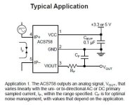
I wonder what the values of the RC is on that board.. I found that if you play around a little with the RC on the output you can get a much better/stable output.. I think this also depends on the value of sensor i.e you can get as much as 50-200mv of noise on the output if no rc is used so on the larger value sensors this can translate into a 3-10A ripple , which is enough to really mess around with the setpoint for the current limit.
 
Supertux1 said:
I'm building a similar circuit for the Bafang BBS02.

Instead of having a PWM RC for the analog voltage out, do you see any issue with using a digitally controlled potentiometer to give the circuit more isolation?

Such As:

http://datasheet.octopart.com/AD5171BRJZ10-R2-Analog-Devices-datasheet-8546.pdf

(Maybe a model with more resolution than that one.)

I have had a quick look and I cant see any reason why this will not work, my only concern with using this would be its a additional chip that controls the throttle position so a high throttle lockout out protection option would need to be implemented, (which should be done even without using another chip). One thing to always remember with anything like this always try to make it fail safe.

My code as it is NOT totally fail safe , but is really easy to incorporate
 
I bought my Teensy boards from the developer's website: https://www.pjrc.com/teensy/ or from Adafruit.

There are reportedly some ebae teensy clones, but I didn't go for that. The cheap Arduino clones are often pretty low quality, not sure I want low reliability in my 6KW throttle circuit. :shock:

For those experimenting with CPU controlled throttle, make sure you have a kill switch under your thumb or ebrakes wired in for safety, a coding error could be fatal.
 
gwhy! said:
Supertux1 said:
I'm building a similar circuit for the Bafang BBS02.

Instead of having a PWM RC for the analog voltage out, do you see any issue with using a digitally controlled potentiometer to give the circuit more isolation?

Such As:

http://datasheet.octopart.com/AD5171BRJZ10-R2-Analog-Devices-datasheet-8546.pdf

(Maybe a model with more resolution than that one.)

I have had a quick look and I cant see any reason why this will not work, my only concern with using this would be its a additional chip that controls the throttle position so a high throttle lockout out protection option would need to be implemented, (which should be done even without using another chip). One thing to always remember with anything like this always try to make it fail safe.

My code as it is NOT totally fail safe , but is really easy to incorporate

I imagine something like what the CAv3 does, you define your ranges for throttle input and if it goes out of that range then its a fault and no output.

I believe the digital pots inputs and outputs are isolated too, so you could actually measure the output of the pot after you set its input and if it isn't the expected voltage/resistance value, then trigger a relay that shuts down the controller.
 
Alan B said:
I bought my Teensy boards from the developer's website: https://www.pjrc.com/teensy/ or from Adafruit.

Thanks.

Supertux1 said:
I imagine something like what the CAv3 does, you define your ranges for throttle input and if it goes out of that range then its a fault and no output.

I believe the digital pots inputs and outputs are isolated too, so you could actually measure the output of the pot after you set its input and if it isn't the expected voltage/resistance value, then trigger a relay that shuts down the controller.

the max value of throttle out will be 1023 = Vs so set output max throttle value for no more than say 950 then if the hall shorts or the ground becomes disconnect this will out put near Vs ( 1023 ) and this will be a fault and you will deal with it how ever you see fit. Also have a pull down resistor on the input pin of the throttle, so if the throttle becomes unplugged this will zero throttle input . if no pull down resistor then this can let the pin float to any value it wants to, which can be upto the WOT value. Yes sample the output of the digital pot to make sure its with in spec.

You will need to fit a resistor in the Vs to a pot throttle it you use this method to protect. hall throttle only tend to output a max of around 85% of there supply voltage.
 
I took a look at the hall effect board I am using and a bit of a surprise. I have a 100 amp and 150 amp unidirectional version of these but upon further inspection I found that they have the bidirectional IC on them and no filtering at all. There is only one component on there besides the chip itself... a very tiny surface mount component between the 5 volt supply and ground. I'm guessing that it is a resistor measuring in circuit about 15 k ohms. I will try adding some filtering on the output.
 
yawstick said:
I took a look at the hall effect board I am using and a bit of a surprise. I have a 100 amp and 150 amp unidirectional version of these but upon further inspection I found that they have the bidirectional IC on them and no filtering at all. There is only one component on there besides the chip itself... a very tiny surface mount component between the 5 volt supply and ground. I'm guessing that it is a resistor measuring in circuit about 15 k ohms. I will try adding some filtering on the output.

i expect that tiny SM is a cap of around .1uf that is required for decoupling on the voltage supply.

hall current sensor.jpg

These current sensors apparently don't like driving a Capacitive load so keep CF small < 0.1 and RF high > 4.7k
 
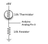
Here is another useful bit of code that can be added for reading temperatures.

arduino_thermistor_circuit.jpg
Code:
double Thermister(int RawADC) 
  {
  double Temp;
  Temp = log(((10240000/RawADC) - 10000));
  Temp = 1 / (0.001129148 + (0.000234125 * Temp) + (0.0000000876741 * Temp * Temp * Temp));
  Temp = Temp - 273.15;           // Convert Kelvin to Celcius
  return Temp;
  }

Void loop()
{
double fTemp;
double temp = Thermister(analogRead(0));
 Serial.print(temp);
  Serial.print(" C /  ");
  fTemp = (temp * 1.8) + 32.0;    // Convert to USA
  Serial.print(fTemp);
  Serial.println(" F");
}

I now use a different lcd library for my nokia 5110 displays ( I used to use the adafruit libraries ) LCD5110_BASIC I found this to be a much better lib as it do not interfere with my sd data logging hardware.

I have also made a few amendments to the current limiting part of the code at the beginning of this thread ( there are also some errors ) that makes the limiting far more predictable and smoother.. I have not posted these amendments but will do if there is any interest.
 
Also another bit of code that peeps may find useful is to read rpm

Code:
                   if ((millis() - msec_rpm) >= 1000) // 1s samples
                   {
                   detachInterrupt(0);    //Disable interrupt when calculating
                   int rpm = rpmcount * 60;  // Convert frecuency to RPM, note: *60 this works for one interruption per full rotation. For four interrups per full rotation use rpmcount * 15.
                   rpmcount = 0; // Restart the RPM counter
                   Serial.print("RPM ");
                   Serial.println(rpm);                  
                   msec_rpm = millis(); // Uptade lasmillis 
                   attachInterrupt(0, interrupt_sensor, FALLING); //enable interrupt
                   }
 
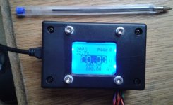
Just thought I would show my 99% completed unit.. for ref.

All the code is basically in this thread ( with a few modifications ) + a few bit that is specific to my setup.

the unit is menu driven has a max-min screen and a debug screen , settable throttle ramps/lvc cutoff and can be torque control or speed control or a mixture of both.
its about half the size of a CA but just as readable and has a back light ( the display looks better in real life than it do in the pic) .

obc_full.jpg
 
looks great. so many project and so little time :) one of those will be the next addition to one of my chargers.
do you have a cheap source for those acs-758? i also haven't found a 20a version which would be great because of higher resolution and just about right for the 1kw charger.
 
izeman said:
looks great. so many project and so little time :) one of those will be the next addition to one of my chargers.
do you have a cheap source for those acs-758? i also haven't found a 20a version which would be great because of higher resolution and just about right for the 1kw charger.

I use Element14 (farnell) as These tend to be the cheapest i have found for the higher current sensors ( postage becomes free orders over £20 )

a quick search on ebay http://www.ebay.co.uk/itm/5V-20A-Range-Current-Sensor-Module-ACS712-Module-ACS712ELC-20A-Chip-For-Arduino-/390959629584?pt=UK_BOI_Electrical_Components_Supplies_ET&hash=item5b07028510
 
I've taken Gwhy!'s code from the 1st post and modified it to my needs:
- RC ESC instead of EBike controller;
- 8x2 i2c LCD interface to display Watts, Volts, AmpHours and Amps;
- Hard-coded current limit;
- I’m using button throttle instead of Hall throttle. However, the input is still analogue, so a twist or thumb Hall throttle can still be used.

The code works perfectly well on my Arduino Nano.
PS. You will need to update the stock LiquidCrystal library to version 1.2 to get i2c capability.
PPS. This is the 1st time ever that I wrote something in C! It was easier than I thought. :D

Code:
//
#include <Wire.h>
#include <LCD.h>
#include <LiquidCrystal_I2C.h>

#include <Servo.h>   //  (rc esc)

#define I2C_ADDR    0x27
#define BACKLIGHT_PIN     3
#define En_pin  2
#define Rw_pin  1
#define Rs_pin  0
#define D4_pin  4
#define D5_pin  5
#define D6_pin  6
#define D7_pin  7

Servo Servo_Pulse; //create servo object

int n = 1;
const int Throttle_Input_pin = A3;  // Throttle input A3
//const int Pot_Input_pin = 6;   //Pot input A6
const int Isensor_Input_pin = 6;  //Isensor input A6
const int Throttle_Output_pin = 3;  //Throttle output D3.. RC filter need is e-bike controller .. no RC filter for rcesc 
const int Voltage_Input_Pin = A2; //A2

const int Set_Min_Servo = 950;  // esc start with this as min throttle default:1000 (rc esc)
const int Set_Max_Servo = 1500;  // esc end with this as max throttle  default:1800. Modify to set your maximum assist speed (rc esc)
int Servo_time = 1000;   // (rc esc)                                                 


long phaseCurrent = 0; // phase current variable; 
const int currentGain = 25; // (25 default) proportional gain setting for current limiting 
// this value sets how fast the system reacts to throttle input, to high a value causes oscillation around the setpoint,
// so need to be mess around with to optimize , same with phasegain value.
const int phaseGain = 6; // (6 default)proportional gain for phase current limiting
const float Current_pot = 450; // un-rem to use a hard codded current limit ( 0-1023 = 0A upto the value of current sensor) 
int Sensor_Cal = 512; // grab real value of this is set in setup section
int throttleCurrent = 0; // throttle setting to achieve current limit
int throttlePhase = 0; // throttle setting to achieve phase current limit
int phaseMax = 0; 
int max_throttleOut = 1023;
int Throttle_Value=0;
int Throttle_Pulse=0;
int Set_Throt_Min = 55; // this needs to be the min value to remove dead band from throttle output , around 55
int Set_Throt_Max = 180; // this needs to be the max value to achive full throttle without cutting out , around 180
int Cal_Throt_Min = 176; // this needs to be set to the real value of the throttle when fully closed;
int Cal_Throt_Max = 842; // this needs to be set to the real value of the throttle when fully open;
float SensorRT=1023; // variable to store value of current sensor. 
//float Current_pot=0;  // variable to store value that sets max current/phase limit. //rem out.. if using hard coded current limits

float Battery_Voltage = 0;
float Battery_Current = 0;
float Power = 0;
float AmpHours = 0;

long previousMillis = 0; //time counter variable
long interval = 1000;  //screen update interval in milliseconds

LiquidCrystal_I2C	lcd(I2C_ADDR,En_pin,Rw_pin,Rs_pin,D4_pin,D5_pin,D6_pin,D7_pin);

void setup()
{
  lcd.begin (8,2); //  <<----- LCD is 8x2

    // Switch on the backlight
  lcd.setBacklightPin(BACKLIGHT_PIN,POSITIVE);
  lcd.setBacklight(HIGH);
  lcd.home (); // go home

    //--- initialize serial communication at 9600 bits per second:
  Serial.begin(9600); 
  // initialize the variables we're linked to
  //   pinMode(Throttle_Output_pin, OUTPUT);   // sets the D3 pin as output // (e-bike)
  //   analogWrite(Throttle_Output_pin,0);  // (e-bike)

  Servo_Pulse.attach(3);      // Attach Servo_Pulse to pin 3  //  (rc esc)
  Servo_Pulse.writeMicroseconds(Servo_time);  //  (rc esc)

  delay(1000);
  Sensor_Cal = analogRead(Isensor_Input_pin); // grabs offset of current sensor that must be connected at power up or the code will not funtion corectly.

  lcd.print("Folken's");
  lcd.setCursor (0,1);        // go to start of 2nd line 
  lcd.print("EBike V1");
  delay(2000);
  
  lcd.print("W      V");
  lcd.setCursor (0,1);        // go to start of 2nd line 
  lcd.print("Ah     A");
  delay(2000);

}

void loop()
{
    // throttle, pot, raw current reading/offsetting
  Throttle_Value = analogRead(Throttle_Input_pin);
  Throttle_Pulse = constrain(map(Throttle_Value,Cal_Throt_Min,Cal_Throt_Max,0,1023),0,1023); // set range on throttle and zero's throttle value
  //Current_pot = constrain(analogRead(Pot_Input_pin),0,1023); // rem out.. if this value is hard coded to speed things up a bit and to free up a adc input
  SensorRT = map(analogRead(Isensor_Input_pin)- Sensor_Cal ,0,1023-Sensor_Cal,0,1023); 
  SensorRT = max(0,SensorRT);

  //Current_pot = (Throttle_Pulse*Current_pot)/1023; // use current pot to set overall max power%
  phaseMax = Current_pot*2;  
  Throttle_Pulse=max(Throttle_Pulse,120); // Throttle pulse uses highest value 
  if (Current_pot < 2)  max_throttleOut=0;  // stop jitter and reset throttle value

  // this routine computes the throttle output required for current control
  throttleCurrent = max_throttleOut - currentGain*(SensorRT - Current_pot)/100;
  throttleCurrent = max(throttleCurrent,0);

  // compute the phase current phase current = shunt current/throttle
  phaseCurrent = SensorRT * 1023 /max(max_throttleOut,25); //set last term to be appx 2.5% of throttle max - throttle min
  throttlePhase = max_throttleOut - phaseGain*(phaseCurrent - phaseMax)/100;
  throttlePhase = max(throttlePhase,0);

  throttleCurrent = min(throttleCurrent,throttlePhase); //choose lower of phase or current throttle
  max_throttleOut = min(Throttle_Pulse,throttleCurrent); // use the lower of current-limited or user requested throttle value

  Throttle_Pulse = map(max_throttleOut,0,1023, Set_Throt_Min, Set_Throt_Max);// scale throttle output limits  
  //analogWrite(Throttle_Output_pin,Throttle_Pulse);  // write throttle to controller //  (e-bike)

  Servo_time = map(max_throttleOut,0,1023,Set_Min_Servo,Set_Max_Servo); // scale output   //  (rc esc)
  Servo_Pulse.writeMicroseconds(Servo_time); //output servo signal to controller  //  (rc esc)   

  
  unsigned long currentMillis = millis();
  if(currentMillis - previousMillis > interval) 
  {
    previousMillis = currentMillis;

    Battery_Voltage = analogRead(Voltage_Input_Pin)/23.4;   //adjust this to get accurate voltage display
    Battery_Current = SensorRT/15.2;   //adjust this to get accurate current display
    Power = Battery_Voltage*Battery_Current;
    AmpHours = AmpHours + (Battery_Current*interval/3600000);

    // erase previous display
//    lcd.setCursor (0,0);
//    lcd.print("        ");
//    lcd.setCursor (0,1);
//    lcd.print("        ");

    lcd.setCursor (0,0);        // go to start of 1st line 
    lcd.print(Power);
    lcd.setCursor (3,0);
    lcd.print(" ");

    lcd.setCursor (4,0);
    lcd.print(Battery_Voltage);

    lcd.setCursor (0,1);        // go to start of 2nd line 
    lcd.print(AmpHours);
    lcd.setCursor (3,1);
    lcd.print(" ");

    lcd.setCursor (4,1);
    lcd.print(Battery_Current);
  }

  delay(100); 

  // DEBUG! Pick whatever variables you want to see, use the Arduino serial monitor
  // to view your values in real time. Tools -> Serial Monitor

  //Serial.print(Battery_Voltage);
  //Serial.print(throttlePhase);
  //Serial.print("  ");
  //Serial.print(Throttle_Pulse);
  //Serial.print("  ");
  //Serial.print(SensorRT);
  //Serial.print("  ");
  //Serial.print(Current_pot);
  //Serial.print("  ");
  //Serial.println(max_throttleOut);
}
 
nice work folken..


here is some more code to help with accuracy ...
its important to know the actual supply voltage to the arduino most call it 5.0v and have done with it but this can cause all sorts of problems with the values that you are expecting when they don't add up. I use this routine to get the real Vcc.

Code:
//---   read 5v supply voltage using the 1.1v reference
long readVcc()
{ long result;
  // Read 1.1V reference against AVcc
  ADMUX = _BV(REFS0) | _BV(MUX3) | _BV(MUX2) | _BV(MUX1);
  delay(2); // Wait for Vref to settle
  ADCSRA |= _BV(ADSC); // Convert
  while (bit_is_set(ADCSRA,ADSC));
  result = ADCL;
  result |= ADCH<<8;
  result = 1125300L / result; // Back-calculate AVcc in mV
  return result;
}

this works on the nano

and to use this code

Code:
  Vcc = readVcc()/1000.0;  // returns actual Vcc of the arduino in Volts

I use this because I am using the supply from the controller's throttle to power the arduino and the supply out of the controller is normally around 4.6v and this makes a big difference in making things accurate instead of assuming its 5.0v :D
 
Thanks Gwhy!
I also thought of using the inernal voltage reference, however, it's 1.1V, so the ADC will only handle voltages from 0V to 1.1V. So the voltage divider has to be adjusted accordingly. I actually need to take a close look at my BEC output voltage first – if it’s not accurate, maybe it’s worth it to use the internal vref.
 
Folken said:
Thanks Gwhy!
I also thought of using the inernal voltage reference, however, it's 1.1V, so the ADC will only handle voltages from 0V to 1.1V. So the voltage divider has to be adjusted accordingly. I actually need to take a close look at my BEC output voltage first – if it’s not accurate, maybe it’s worth it to use the internal vref.

It only uses the 1.1v ref to work out the actual Vcc being used.. i.e when powering the nano from my usb on my pc is 4.8v , when powering it from the e-bike controller its 4.6v and if i use my bench psu for testing thats 5.2v.. the code that I have posted will always give you the real Vcc instead of just using a fixed 5v in your code. So using the code posted you dont have to worry about small changes in the Vcc and you still get to use all of the available resolution i.e 0-Vcc instead of 0-Vref. I call this code at power on or when ever the arduino is reset then just use the returned value of Vcc in all my code instead of assuming that its 5v

Edit:

if you want accurate voltage reading and current readings then you mush know the exact Vcc .. Also with the Hall current sensors you will also use the actual value of Vcc to adjust the actual mv per Amp spec of the sensor being used
 
OK, I got it now! I didn't think that measuring VCC was actually possible. And you're right, it's crucial for accurate current readings. I'll definitely try that code.
 
I've just found out that varying the 5V VCC supply has no effect whatsoever on current readings if Hall sensor is used. The reason being, the sensor's maximum output is staying the same as the ADC maximum input: both equal VCC. Very convenient!

When measuring battery voltage, however, the VCC voltage variations have immediate effect, because the battery voltage does not necessarily vary with varying VCC.

The code above works, but the readings were not very accurate in my case - I suspect each individual MCU has small variations of its internal reference voltage regulator output. This can be easily compensated for in software - you just need an accurate multimeter to calculate the correction coefficient.
 
Yes there are small variations in the ref voltage between each processor but overall makes it far more accurate than assuming 5.0v for Vcc if using different PSU's.. Hall sensor sensors have a mV per A value and this is calculated for a fixed 5.0v Vcc .. it very much depends on how far out your Vcc is from 5.0v on the processor to how accurate the readings are, this is more high lighted if the total available range of the sensor used as the more current pulled through the sensor the less accurate the readings become .. use a sensor and power it with exactly 5.0v then feed 1A through it and measure the output ( it will be what it says in the spec sheet , in my case 20mv) now reduce Vcc and the 20mV will proportionally drop even though its still 1A flowing, ok its not a lot different but over 200A in my case, it adds up to quite a bit .

edit:
I suppose it very much depends on how your code is used to get the current reading to how it effects the your total..

I have a couple of nanos and minipro's here and I will test the v ref on them to see how they all stack up, and post results here.
 
The mV per A rating of a Hall sensor (at least the one that I'm using) varies with its supply voltage. That is, at 0A the output sits at exactly half VCC (whatever it is), and at full rated current the output voltage is either at 0 or at VCC, depending on the current's direction. Likewise, the ADC's middle point (511) is exactly at half VCC, whatever the VCC is - if you're using VCC as ADC's reference of course! Which is Arduino 's default ADC setting. And 1023 will be at VCC. The ADC's input is tracking Hall's output automatically. There is nothing to compensate for. My ESC's BEC output was 5.7V feeding Arduino and Hall directly (oh sh...!), and then I connected it through Arduino's LDO which gave me 4.9V instead. And guess what - my battery voltage readings became way off and had to be compensated for the decreased VCC, but the current readings remained spot-on as before.
 
Folken said:
The mV per A rating of a Hall sensor (at least the one that I'm using) varies with its supply voltage. That is, at 0A the output sits at exactly half VCC (whatever it is), and at full rated current the output voltage is either at 0 or at VCC, depending on the current's direction. Likewise, the ADC's middle point (511) is exactly at half VCC, whatever the VCC is - if you're using VCC as ADC's reference of course! Which is Arduino 's default ADC setting. And 1023 will be at VCC. The ADC's input is tracking Hall's output automatically. There is nothing to compensate for. My ESC's BEC output was 5.7V feeding Arduino and Hall directly (oh sh...!), and then I connected it through Arduino's LDO which gave me 4.9V instead. And guess what - my battery voltage readings became way off and had to be compensated for the decreased VCC, but the current readings remained spot-on as before.


as I said it will depend on how you have coded to how it will read... I use a 200A uni sensor and at 20mv/A @ 5V and this don't add upto 200A it can actually read around 230A after the offset has been removed .. there is more than one way to skin a cat :D

Edit: If you take the value of the sensor literary then yes you can just divide the value by 1023 ( or in your case 511 ) and use the ADC raw values to work out current, or better still just use the map function in the code as this will get ride of a lot of messing about. i.e in your case

Code:
current= map(sensorRAW,511,1023,0,sensor value );  //for positive values this swill give you a direct reading in amps when sensor value is the literal value and for negitive values use current=map(sensorRAW,0,511,sensor value,0);
 
Back
Top