Through-the-Gears Project & OT Hydraulic Power Transmission

Solcar

10 kW
Joined
Jan 7, 2010
Messages
508
Location
Ohio River Valley
I have done some evaluation on the service capability of the gearbox (http://www.herbach.com/Merchant2/merchant.mv?Screen=PROD&Store_Code=HAR&Product_Code=TM92MEC1999)
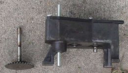
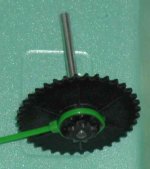
I have been using on my ebike. I've put about 5000 miles on it over about 14 years. I have never put more than about 300 watts through it. When I took it open lately to work on replacing the output shaft with a new, longer one machined to accept one of those common 15 tooth freewheeling sprockets
(http://www.electricscooterparts.com/SPR-2515F.htm)
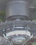
for #25 chain, I noticed that the gears have worn to the point where breakage appears to be likely before long. The teeth are probably worn by 50%.

That leads into my wondering about the idea of a hydraulic transmission to transfer power from the motor to the wheel. I can surmise that efficiency would be lower. Who else has wondered some about the feasibility of using a hydraulic tranny? It ought to be able to give a lot of load matching (in a gear reduction sense) if nothing else.

http://en.wikipedia.org/wiki/Hydraulic_bicycle

:?:
 
It'll be complex and weigh a bit I think. You'd need a variable displacement pump, a fixed displacement motor, a bypass so you could freewheel, an oil cooler, a filter, a reservoir and hoses.

You might check out www.hydraulicinnovations.com They build 3-cyl diesel motorcycles w/ hydrostatic transmissions. 8)
 
http://world.honda.com/motorcycle-technology/hondamatic/p6.html
 
Thanks for those responses. I saw in some of the information from those links that piston compression was employed. I was thinking they'd use vane or something.
 
I have been using the latest from-scratch through-the-gears ebike version pretty successfully. The motor/gearbox assy originally was located behind the seat post and partially underneath the seat, offset to the right somewhat. This spring, I made a new output shaft for the gearbox that I got from Herbach and Rademan for c. $15.

herbach and rademan gearbox.jpg

I then moved the drive assy forward on the bike to just behind the head tube.

I just have basic tools like drills, visegrip pliers, and hacksaw blades, but the three shafts that the gears of the gearbox rotate on are standard 3/8 steel rod, so hand machining substitute ones with crude tools is quite possible.

What I did this spring (4/2011) was fashion a new output shaft that was about 3/8" longer at the output so that a longer sprocket with a freewheel could fit. It worked well except for the problem of the start-up torque causing the freewheel to skip.

Recently it occurred to me that I can try to move the freewheel to the input shaft of the gearbox to reduce the torque it must withstand. The gear action of this gearbox is very quiet and efficient, so I don't expect a considerable increase in either rotational drag felt at the pedals or noise.

It will require machining a new input shaft, but the stringency of the needed result should be less (less demanding specifications) because of the reduced forces that it has to endure. The only really iffy thing is that the longer sprocket will require the mounting position of the gearbox on the bike to be altered to make room.

Presently, the gearbox provides a 23:1 reduction from the motor to the output. The 15 tooth #25 freewheeling sprocket on its output drives a 90 tooth mounted onto the chainring assy for a total reduction of about 140:1. The motor is a Pittman brush servo with a KV of 233. I find that the present electric assist wants me to pedal faster than I prefer.

If I didn't want to gear down the electric drive further, I could get by with the freewheel skipping problem by being easy on the throttle from a stop. But I wish to increase the reduction ratio up to 200:1 or more. This will also prepare the system for more overvolting of the motor that the new controller assembly is to provide.

Edit: it tells me the image file is gone, so I reuploaded it at the bottom.
 
I opened up a gearbox to remove the original input shaft to pattern a new but altered one after. After lifting the back cover off the rest of the parts, I heard a "tink" as one of the c-clips had stuck to it on account of a coating of grease on it and then let go, falling, and striking a small box wrench and then flying off somewhere. I wasn't able to find it. :( My right ear is kinda weak, so my aural zeroing-in ability ain't what it used to be.
 
Above I uploaded a before picture as bought from H&R. Here is it with the new input shaft. The old shaft is at the left.

The shaft is extra long while I think about and try input set-ups. the input shaft is to have the freewheel on it, and they don't like any sideways pressure on themselves. So, the freewheel must be fed by chain, meaning the belt input will need to be a separate earlier stage.

The hole on the original input shaft that held the pin for its gear is visible in the middle of the shaft's length. That is the hole that needed to be perpendicular in two dimensions on the new shaft.
 

Attachments

  • q-rsz_old_shaft_and_new_one_installed.jpg
    q-rsz_old_shaft_and_new_one_installed.jpg
    26.7 KB · Views: 2,373
The gearbox has a solid structure that I am in the process of adding a reduction stage to. I expect this prestage to have a gain of just 2.25, with a 16t #25 plastic sprocket on the motor connecting to a 36t plastic sprocket via a plastic chain. That 36t sprocket is part of a jack shaft mentioned below.

The 36t sprocket can then be affixed to something like a 14 or 15 tooth sprocket that, via plastic chain, goes to 42t plastic sprocket attached to the sprague freewheel that rides on the input shaft. I have some such freewheeling sprockets whose bearings ride on a 3/8" shaft, which is what this gearbox uses. Longevity of the soft steel input shaft might be questionable, so i might have to change that later.

I hope to increase the net total gearing of these stages from the present 24:1 up to 40:1.
 
I was pleased with the digital calipers that i bought for less than $9 with some 1/4" X 3/8" X 1/8" bearings from VXB Bearings. It seems like maybe it really can measure down to 10 microns.
 
Latest on the through-the-gears project is that the new input shaft is installed in the gearbox.

I am leaning toward just keeping the 15 tooth sprocket at the input since it is the one built onto the freewheel which I am placing on the input shaft of the gearbox. That means that I will need more reduction earlier on in the set-up than I was planning on because the gearbox stage will just have a gain of 4, down from the 13 I had before with 36 teeth on the other input sprocket. Also, the output sprocket on the gearbox is now slated to get 20 teeth: 15/20 * 5.3 = 4, before: 36/15 * 5.3 = 13.
 
Just an FYI - I built a through-the-gears ebike and put the "motor" freewheel down on the BB. That freewheel separates the motor-driven chainring from the pedal one. That way you wouldn't have to backdrive the reduction unit or power chain. I have used it for 2 seasons now. It probably has 1500+ miles on it without any major problems. You can read about it here http://endless-sphere.com/forums/viewtopic.php?f=28&t=15529
 
A freewheeled crank is something I wouldn't mind having. I have been unable to do it though. I have been in a position concerning this project where I have to leave off features unless there is no real choice in the matter as far as usability goes. I find some important things for this project are low dollar cost, functionality to carry me and items, mainly food, in warm weather, and it being not more complicated than I can get away with. I'm going to look at your thread though :) , thanks!

Someday, I may build a new system on an old Front Freewheel System (R) http://en.wikipedia.org/wiki/Front_freewheel bike that was on the market a few decades ago. It boils down to whether I got plenty of spare time or not.

I have reconsidered, and now I am piggybacking a 36 tooth (#25) sprocket onto the 15 tooth one on the freewheel. That will take the gain of the stage from 4 to 8, and lower the force on the chain to it enough to be able to go with easy-to-use and quieter plastic chain. With plastic chain, the links pop apart and back together again for easy length selection.
 
I now have mounted the 36 tooth plastic sprocket onto the 15 tooth freewheel sprocket using 14 gauge soft steel wire. There are 6 holes drilled evenly spaced around the inner circumference of the plastic sprocket. Those holes are used in pairs, with the 14 gauge wire being used as staples with fingers that pass through the plastic sprocket and claw around a 3/8" long, c. 1" diameter PVC pipe spacer, to be kept from slipping by 6 of the 15 teeth of the freewheel sprocket. This was easiest way to lock the 36 tooth sprocket to the 15 tooth freewheel sprocket. I didn't do very well with the picture so I lowered the contrast to try to get the fingered staples to show up better.
 

Attachments

  • q-piggybacked.jpg
    q-piggybacked.jpg
    7.9 KB · Views: 2,373
I had an opportunity, and worked on a jackshaft whose small output sprocket is to be connected by a chain, probably plastic, to the gearbox input sprocket/freewheel assembly. The larger 36 tooth sprocket on the jackshaft is to be driven through a plastic chain by something like a 16 tooth sprocket on the motor.

To make the jackshaft, I drilled a pinning hole near one end of a circa 5" long 1/4" steel rod, and slipped an 8 tooth steel sprocket over that end, lining up the pinning holes. That little 8 tooth sprocket happens to have an outer diameter of 3/8" on the (flange) portion that doesn't have teeth.

I removed the set screw from the new 36 tooth plastic sprocket and slipped its 3/8" mounting hole over the flange of the 8 tooth sprocket, lining up the set screw hole with the pinning holes beneath it. An appropriate-sized piece of nail passes through all of the holes.

(I wrapped a small piece of electrical tape around the end of the nail piece that will press against the inside of the set screw hole to protect the threads from the nail steel. I wrapped more electrical tape around the 1/4" shaft to support the 3/8" inside diameter free end of that 36 tooth sprocket.

I jammed a short piece of nylon zip tie into the set screw hole next to the protruding nail piece to keep the nail snug in the hole and used a zip tie to prevent centrifugal force from making the nail piece fly out.

I still need to make a bearing assembly and mount the jackshaft onto the side of the gearbox.

I should end up with a mechanical gain of 2.25 * 5 * 5.3 for a total of about 60. That seems good because I have been wanting to be able to pedal slower and still contribute about 1/3 to 1/2 half of the work needed to move the bike and luggage.

Edit: I just installed a new image resizer (Mihov Image Resizer freeware gotten from CNET's downloads), and it is able to lower the quality to a level that makes more sense, given that the focus on my camera is usually too poor to warrant the my image file sizes that were here. So, I deleted the pictures in this thread and re-uploaded the reworked ones.
 

Attachments

  • q-DSCI0053.JPG
    q-DSCI0053.JPG
    21.9 KB · Views: 2,373
:) Thanks Matt! I have been having a good time evolving it. I actually was thinking about the efficiency recently and it reminded me of a power wheels transmission in that this project gearbox assembly has about a 60:1 total reduction compared to about 120:1 for a power wheels unit. Another comparison is that mine handles about 10 times more power, at least, and still has probably only 1/3 the percent transfer losses that a power wheels transmission has. Another similarity is an unusual amount of plastic cogging along with plastic chains.

I could have pretty normal efficiency for an ebike if I were to not have an 8 tooth sprocket in the reduction train, but that jackshaft went together kinda elegantly, so I just couldn't resist using those parts that way. I also like how the 8 tooth sprocket really pushes the total gear reduction figure up by a big jump.

On the other hand, the planned first stage combining a 16 tooth on the motor with a 36 tooth sprocket on the jackshaft tends to give the efficiency a little boost toward the better end. So maybe that will tend to offset the loss from the 8 tooth sprocket.

I have been really impressed with your gear reductions, and another recent musing had me actually pondering how one one your gear reductions would fit into my project somehow. That consideration will likely remain in my mind in the future, too.
 
I haven't gotten much opportunity or motivation to install that revised gearbox assembly, partly because I've decided to mount a 13 tooth freewheel directly onto the stock finger piece on the output shaft of one of those 5.3:1 gearboxes. I will still need to add a lot more reduction to an input stage of the gearbox before mounting it in front of either of my two crank sprockets and running a 1/2" - 3/32" chain between the 13t freewheel and one of the crank sprockets.

My present strategy is to have the pedals be turned, but rather slowly, by the assist. It would turn about 1/2 rotation per second and wouldn't be freewheeling.

I'm thinking about the extra reduction at the input of the gearbox being done using friction drive. Instead of there being a sprocket or pulley on the input shaft of the gearbox, there would be friction disc that would be turned by an abrasive cylinder on the motor shaft.
 
I didn't have a chance to work on the drive update this spring so now I am sweating it out as I can. Because I am using an input 8 tooth drive sprocket out of convenience due to it fitting into the project easily, I expect the noise to be higher than previously expected, as well as the wear on the chain and sprockets.

However, the mechanical gain should be huge, and though that will turn the pedals slowly, the forces on the final drive components can be great enough to break stuff. But the motor should be able to spin up to the point where it can maximize its output power with lower losses.
 
Finally got the revised gearbox ready to try and rode the bike about 20 feet before the new jackshaft fell apart. It turns out just wrapping tape around the 1/4" diameter rod that the sprockets are affixed to doesn't give a sufficient interference fit to the bearing (the one near the sprocket) to hold the thing together. Makes sense to me now that it brought itself to my attention. I would have needed to have the shaft be enough longer so that a c-ring could have been placed on it at the far end where the surrounding sleeve ends.

Editing here now (sept 2) because I'm not sure what I'm going to do next since now about a month after that Aug 10 post, I finally got it all reinforced and braced just to shear off the pin through the final reduction stage gear. I had removed a pedal so I could spin the wheel on the floor during an inside test and was letting it spin when the gearbox failed.

Sept 8: Making a new output shaft for the gearbox because the nail that had been the pin was proving too hard to drill out. Thinking about using keyway type set-up rather than a pin through the shaft, which should be stronger.
 
Back
Top