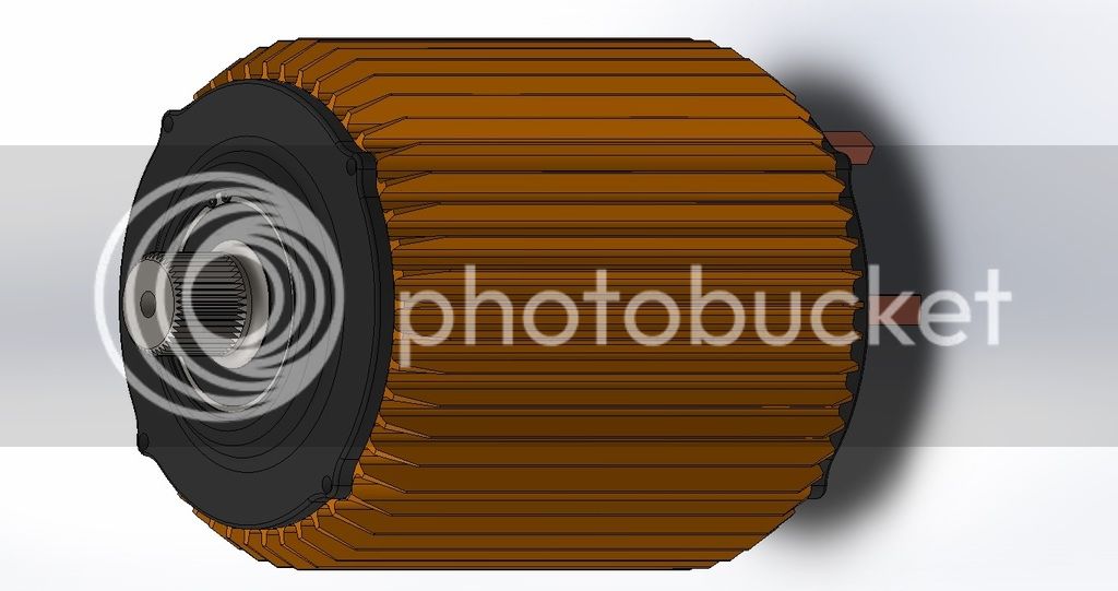
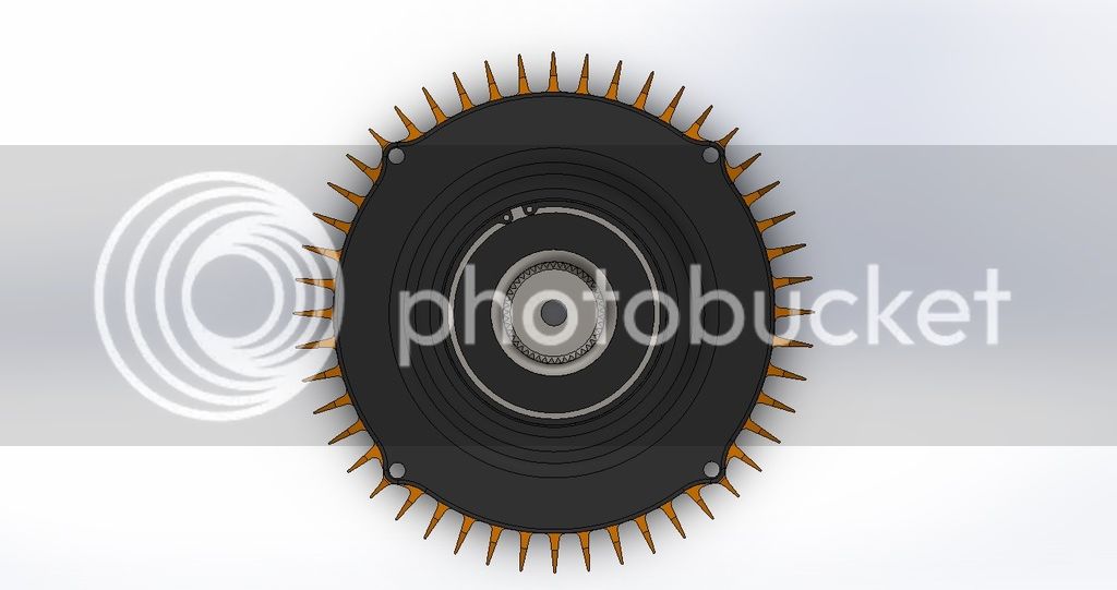
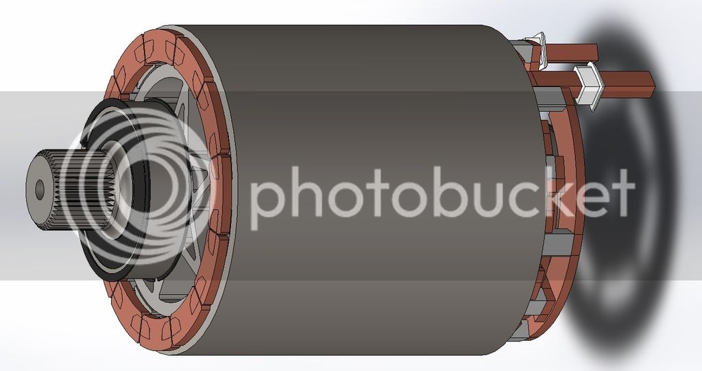
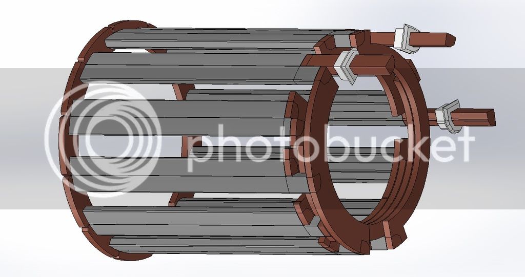
Triple solid slot Zero 75-7

Lebowski said:
Nuts&Volts said:
Lebowski said:
Each of your 6 controllers needs to know there are 5 others driving the same stator teeth, else your FOC won't be correct.

The sevcon controllers have a master/slave setup that allows them to parallel up. I've seen two on one motor, but pretty no one has done 6 before.

Is this only to share throttle information or does each controller how many others there are and what relative phase they have (whether they are on the same teeth or whether some are 30 degree offset ?) ?

I would expect in a master-slave setup that one controller would do the FOC calcs and the others would synch the waveforms to the master, But that's a guess. Sharing throttle would not be enough.
 
Omg guys that is exciting !!!
I am havent read E-S since a week due to my trip to Taiwan for my work.

What a big surprize! Definitivly subscribed !!!

A sexto 75-7 :shock:

I guess it will me more efficient due to the reduction of the number of winding end from 12 to only 2 ends

Will you keep it sin/cos or change to UVW ?

If sin cos i guess it will be more difficult to perfectly match all 6 rotor angles and get perfect matched sinwave?

The chime of the harmonic sound will also change alot due that 6x longer rotor and lower resonant frequency axial mode... i am curious about the result!

Keep up the good work!!

Doc
 
Doctorbass said:
What a big surprize! Definitivly subscribed !!!
lol. same here. and i just subscribed because i want to follow this amazing project and maybe learn something. not that i ever would think about electric motors pulling over a 1000A and giving hundreds of kW. :)
 
Hi,

Is this useful?:
http://endless-sphere.com/forums/viewtopic.php?f=30&t=56786
Walk-thru w/Pictures - Hand-building a Spark EV Motor

GM builds its own oil-cooled permanent-magnet electric motor for this Spark at a plant in Baltimore, a motor it promises will appear in another, as yet unnamed, product in the pipeline. Take note: One day it could be remembered as the small-block of the electric segment.

Instant Electric Torque, and Lots of It
It spins out 105 kW (140 horsepower) and a strong 400 lb-ft of torque. That latter figure, especially, makes us think it's past time the Society of Automotive Engineers (SAE) weighed in with a standard for reliable comparisons, but once you drive it, there's no question this motor's got muscle. Car and Driver estimates the Spark EV can reach 60 mph in fewer than eight seconds

In essence, the stator is a tube consisting of electrical steel and copper. The steel portion has a high silicon and iron content and consists of many thin plates called laminations. Slots in the laminations are first lined with insulating sleeves made of paper and then filled with approximately 20 pounds of copper. Instead of using round-section wires, GM’s design for the Spark’s motor fills the stator slots with rectangular-section copper bars. (The roughly 3-by-4-mm bars have a higher surface-to-volume ratio than round wire, which optimizes both their electrical and cooling characteristics.)....

GM uses a two-lever press to form the copper bars to the desired shape. After loading a straight chunk of varnish-coated copper bar stock into the die jaws, I gave the first handle a hefty swing followed by a pull of the second lever. Upon returning those handles to their original positions, the finished product—what looks like a hairpin for Andre the Giant—is ready for further processing.
GMs-two-lever-press-in-action-626x382.jpg


The next step is carefully loading 120 of those hairpins into the correct stator slots. There are eight types of pins and they fit closely together, so care is needed to get the location and sequence perfect. After the pins are started, they’re shoved home—seated all the way inside the stator—in a hydraulic press exerting more than 1000 pounds of force to overcome the friction between the copper bars and the paper insulators.
Loading-wires-into-the-stator-626x382.jpg
 
Farfle said:
It seems I am mistaken. Excellent.
Punching it into emetor with a different motor. I get
10mm Length 6t stator: .117. mH
60mm Length 1t stator: .0116 mH

I think the formula is:

inductance initial * (Turns final / Turns initial)^2 * (Stator Final / Stator initial) = inductance final
.117 * 1/6^2 * 6 = .117/6

Which give .0195 mH (emotor is probably more precise, magnetic fields, end turns, etc.)


Next year we'll have 2x 75-7 motor per wheel (8 total), 500 hp @ wheels AND torque vectoring!!! :lol: 8) :!:
 
Heya all, quick update. Luke is letting me borrow a super baller Red Pitaya LCR meter, so I am going to test wind a motor with some normal 14g wire with a few different test winding schemes. and get a rough ballpark of what the inductance will be.
 
don't forget to put the rotor in place to measure it properly
 
h0tr0d said:
don't forget to put the rotor in place to measure it properly

hmmmmm. that is very difficult The uncased laminations are very fragile, and the rotors are incredibly feisty..

Is that a linear enough relation ship that i can measure a single motor with and without rotor, get the ratio and then use that on the new motor?
 
Farfle said:
The stock 75-7s are 6 turns of 24 paralell strands of 18Awg.

Farfle, Are you aware of the two different versin of the 75-7 ?

There is one for the 2013 and one for the 2012 witch i guess have less turn in the winding.

I have installed the stock "2013+" 75-7 on my S 2012 and i get alot of torque.

If the 2013+ version for the 28s battery of the 75-7 is 6 turns of 24 paralells strands of 18Awg i guess the 2012for the 18s battery have less turn.. maybe 4 turn? do you have the data of this 75-7 motor version?

Doc
 
Doctorbass said:
Farfle said:
The stock 75-7s are 6 turns of 24 paralell strands of 18Awg.

Farfle, Are you aware of the two different versin of the 75-7 ?

There is one for the 2013 and one for the 2012 witch i guess have less turn in the winding.

I have installed the stock "2013+" 75-7 on my S 2012 and i get alot of torque.

If the 2013+ version for the 28s battery of the 75-7 is 6 turns of 24 paralells strands of 18Awg i guess the 2012for the 18s battery have less turn.. maybe 4 turn? do you have the data of this 75-7 motor version?

Doc

yeah, the 2012 retrofit motor is a 4 turn. It cant spin much faster though because of the sevcon's ERPM limit.
 
Farfle said:
h0tr0d said:
don't forget to put the rotor in place to measure it properly

hmmmmm. that is very difficult The uncased laminations are very fragile, and the rotors are incredibly feisty..

Is that a linear enough relation ship that i can measure a single motor with and without rotor, get the ratio and then use that on the new motor?

I know it's difficult...

If a sevcon can handle a 4t, single stack, that's .117*(4/9)=. 052mH

Using sevcons, you'll probably have to make two triple motors...
 
Thanks for sharing this farfel. I think I found a reason to make a trip down :)
 
Man that motor you are building will be a real beast. not to mention what it will do with a lightweight car :twisted:
I wish you success! will follow this awesome project with lots of curiosity^^
 
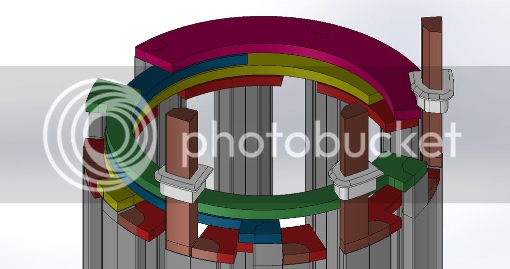
Heya all! quick update. The CAD model for the new motor is done, and it looks awesome. The winding config is 1T with both halves in series, whereas stock is 6t with both halves in paralell. The phase leads will be a machined copper buss that is roughly 125mm^2 cross section. These shaped busses will be joined with waterjet cut "end turns" that will be TIG welded, or copper bolted in place.


So awesome Farfle!!!! You ROCK!!
 
Nice work.

So all you will keep is the original rotor and heatsink stack?

Doc
 
Doctorbass said:
Nice work.

So all you will keep is the original rotor and heatsink stack?

Doc

All that is being kept is the stator lams, and the three assembled rotors will be mostly untouched. I am unsure about the case on the motor, as I destroyed the existing aluminum cases getting the stators out. The ID is 204.9mm and a press/heat fit to the 205mm stator, as well as a couple of set screws. not too hard to duplicate.
 
A solidslot motor! Watch out for eddy current losses in the conductors. In most motor designs the cross section of the winding wire is small enough to neglect eddy currents. Not sure if the tooth profile needs to be different for a solidslot motor, as to "shield" the conductors. Looking at a REMY motor with a hairpin winding makes me think you are likely OK, but just throwing it out there.

http://eprints.whiterose.ac.uk/9077/1/Zhu_Influence.pdf

Note the 1 strand winding has 35 turns
 
flathill said:
A solidslot motor! Watch out for eddy current losses in the conductors. In most motor designs the cross section of the winding wire is small enough to neglect eddy currents. Not sure if the tooth profile needs to be different for a solidslot motor, as to "shield" the conductors. Looking at a REMY motor with a hairpin winding makes me think you are likely OK, but just throwing it out there.


It will be an awesome and interesting learning experience to see how all the losses stack up. I have a feeling that the main dominant loss (I^2R) being reduced so drastically will make up for the other potentially increasing losses.

The stock motor has each half as 12 strands of 18awg, and the two halves paralelled for 24x18awg total. each 24x18AWG phase lead is 19.752 mm^2


If the new motor was wound with wire to match the stock amount, it would have 1/6th the turns, which would be 118.51 mm^2, but both halves are in series, so it would only be 59.26 mm^2


With the solid-slot design, SW is saying the cross section will be 124 mm^2, but that is assuming a .5mm nomex insulation wrap, and that the buss bar is a perfect fill in the slot. My machining is not perfect, so I will assume that the windings should be somewhere around 110 mm^2, which is almost double the round wire copper fill :shock: :shock: .
 
Farfle,

What's your time frame on this? I'm interested in sponsoring you with some machine work if you can wait 2-3 weeks.

-Cole
 
http://eprints.whiterose.ac.uk/9077/1/Zhu_Influence.pdf

Note the 1 strand winding has 35 turns (2.65mm) is the thickest they try and you can see the AC losses started to rise faster and faster as the wire size goes up

Don't let this stop you but just something to think of when sizing the conductors. You may want to keep them away from the maximum leakage flux area in the slot
 
coleasterling said:
Farfle,

What's your time frame on this? I'm interested in sponsoring you with some machine work if you can wait 2-3 weeks.

-Cole

That would be awesome, The timeframe is (roughly) to have it in a running car by next year, so the motor build will probably be ~5 months.
 
Back
Top