Troubleshooting a Crystalyte hub motor

SpeedEBikes

100 W
Joined
Sep 4, 2009
Messages
165
Location
Chicago
A hall sensor got zapped in a Crystalyte 407/409. Not knowing how to unpot and replace the sensor, and just happening to have a second rotor on hand I swapped the rotor.

The motor runs but not smoothly and it's drawing far too much current without a load. I just recently bought an oscilloscope so I hooked it up to see if I could see anything obvious amiss. I've attached a screenshot of the scope showing the hall sensors on the digital logic inputs at the top of the screen and the voltages across the first two phase wires (yellow and green). I took a second shot capturing the green and blue phase wires and it looks very similar.

This is with an old Crystalyte analog 20 amp controller being run on a battery at 50 volts.

Does this trace suggest a problem? I'm wondering whether it is typical for the active phase's signal to diminish this much when the successive phase kicks in? Also, there is the spike while one phase is off and the successive phase cuts off. Any suggestions for further troubleshooting?
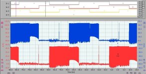
crystalyte_yg.jpg
 
when a motor rins but it runs rough and eats lots of amps it can only mean one thing. the hall sensors do not match the phase wires.

you need to do some swaping of phase and/or hall wires to find the correct combination. think of it this way. the hall sensors are like the distributor in a gas car. on a V8 you could swap a pair of the ignition wires. the motor will start and run, rough as hell and spitting raw fuel out of the exhaust it will use way too much gas.

rick
 
Rick,

The hall wires are red(power+),black(power-),yellow(phase1),green(phase2),blue(phase3) and I have three matching yellow green and blue phase wires. Actually there are two sets of matching phase wires as the rotor is a dual tap 407/409.

On the hall sensor wires I've tried swapping yellow and green, yellow and blue and green and blue. Each made the motor fail to run at all.

However, I've just this second realized that I have failed to try rotating all 3 and that now strikes me as very likely the problem. I can see from the traces that the phases are energized in an overlapping fashion and it looks like the phases are energized correctly for 2/3s of their on time but are getting hammered down in voltage for the last 3rd (probably drawing excessive current then as they pulling toward the wrong magnet). At least I hope that's right. I'll be testing it shortly.
 
I've tried the 3 rotations of the phase wires and two result in rough running and one results in the motor running smoothly in reverse.
 
sounds like you got your timing problem almost solved.

if it runs smooth in reverse, you can also reverse at the connector. pick any pair of phase wires. swap them for each other . then swap the matching hall wires.

that will reverse the order of progression and the motor.

the color codes for these things is aparently optional. that is why there is a section on the forum for known to work motor/controller combinations that includes the color combinations. very often the colors do not match.

rick
 
I did the swap of a pair of phase wires and the matching hall wires and all is well now. I once had instructions that I can't find now for putting a jumper (or removing one) in the controller for reverse.
 
which controller is it? one of the old Crystalyte Analog 20A ones? somewhere on the forum this was discussed ages ago. i would suggest a search on the forum.

rick
 
also in the technical reference section of the forum there is a thread by someone describing how to replace the sensors. he's using a 9C in his example. but the same basic instructions work for almost all motors. lots of pictures. very pretty pictures. might be useful to fix that rotor up and have a working spare.

rick
 
Yes, it is one of the Crystalyte analog 20 amp units. I tried a search but didn't find anything for putting a reverse switch on it. Now that I have it wired up ok for proper forward use a reverse switch is less important although if I knew how to do it I would.


rkosiorek said:
which controller is it? one of the old Crystalyte Analog 20A ones? somewhere on the forum this was discussed ages ago. i would suggest a search on the forum.

rick
 
Thanks again rick! I did more searching and found this thread.

http://endless-sphere.com/forums/viewtopic.php?f=2&t=2451

It turns out no solvent at all is needed for the epoxy. It gets soft at 100C. I'll give it a shot with a heat gun and if I'm successful I will order some replacements.

rkosiorek said:
also in the technical reference section of the forum there is a thread by someone describing how to replace the sensors. he's using a 9C in his example. but the same basic instructions work for almost all motors. lots of pictures. very pretty pictures. might be useful to fix that rotor up and have a working spare.

rick
 
That is good SpeedEBikes because it is quite difficult to find solvents that work on cured Epoxy. Even heat will destroy it but in this case it doesn't really matter as long as you get the bad sensor out! Good luck!
otherdoc
 
Back
Top