Ultra Cheap 66160 30Ah LTO - Or Scam?

Yeah. I have purchased those resistors I linked above.

Unfortunately, even with expedited shipping ($25 to ship 5 x $1.50 resistors!) it'll still take a week to get here. So in the mean time, I'll just build the pack, and I'll have to take it back apart to do more testing.

Sorry for the delay guys, I hadn't thought this through well.
 
Hillhater said:
mushymelon said:
For example a toaster oven is tuned for lets say 800 to 1200 watts 110 V AC, they do this by the length of the wire.

For DC you would need Double the voltage or cut the wire in half and parallel the connections. 110V dc paralleled to get the same 800 to 1200 w

Cut the same wire into 4 parallel connections and you get same watts at 55v divide it into 8 and 27.5V and so on.
.

This gets a little tricky for us guys down here on 240v domestic mains....900W toasters
..and even more so if you are testing a single 2.4v cell like Sunder has.
I think it would need A lot of parallel sections to get to a 3v DC, 800-1200W system ?

Could there be step-up converters that could work as low as 2 volts ???
I wonder.

I got myself a Ming He BST900 (awesome!), supposed to do 900W and I can adjust it up to 120V...
Now is the could do this with 2.4Volts.... I could make things eassier.
 
Matador said:
I got myself a Ming He BST900 (awesome!), supposed to do 900W and I can adjust it up to 120V...
Now is the could do this with 2.4Volts.... I could make things eassier.
No matter how low it goes, converter will be limited by max. current anyway. Is it 15A for BST900, being 15x2.4=36W?
 
parabellum said:
Matador said:
I got myself a Ming He BST900 (awesome!), supposed to do 900W and I can adjust it up to 120V...
Now is the could do this with 2.4Volts.... I could make things eassier.
No matter how low it goes, converter will be limited by max. current anyway. Is it 15A for BST900, being 15x2.4=36W?

Yes, makes sense. BST900 is not best suited. Had hopes for low voltage step up converters that could handle more amps...
 
ok so waiting on some results on quality / performance. At this price, a battery pack for my home solar is looking very good indeed.

48V nominal is what my inverter wants to see. With a range of 40V to 55V ish. I have found a BMS with programmable balancing voltage ranges, however it will only monitor down to 2.2V which is perhaps a bit low for LTO.

Anyway, for this pack 90Ah, needs 3 cells in parallel, and 3V max, 1.5V cutoff? will need 20 Cells in series, which raises an issue, I am pretty sure 30V min and 60V max is outside the operational ranges of the inverter. I could get 19cells for VMax = 57V, but only discharge them to 2.2V (this is the lower limit of the BMS) That could work, but I will reduce available capacity (increase longevity), Thus I need 19 x 3 = 57 cells, " $22USD / cell = $1254.. fantastic for a 48V 90Ah pack.

so my main question is.. if this is a cheap, and L O N G lifespan lithium technology, why don't home solar OEM's use it. instead they use some quality 18650, rated at 1000 cycles, but resulting in a battery with only 50% capacity at the end of 9 or 10 years. It seems to me that this technology is superior. we don't need to worry about space or weight for home solar storage..

Do you have the link to your supplier?

Thanks
Andy
 
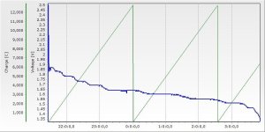
I have done one complete logged cycle with the first LTO cell.

LTO Cell 1.jpg

Ignore the actual cell voltages. The Imax B6/B8s tend to read too low a voltage when discharging, and too high a voltage when charging. The correct start of the graph is 2.5v, and the correct termination is 2.0v There must be excessively high resistance between the battery and where the voltage is being measured, but at least it's a consistent 0.7v @ 5.0amp discharge.

I also tested the resistance of the cell in the bulk discharge voltage part of the curve. The cells are only around 2-3mOhm. So all looking good!
 
Animalector said:
so my main question is.. if this is a cheap, and L O N G lifespan lithium technology, why don't home solar OEM's use it. instead they use some quality 18650, rated at 1000 cycles, but resulting in a battery with only 50% capacity at the end of 9 or 10 years. It seems to me that this technology is superior. we don't need to worry about space or weight for home solar storage..

Do you have the link to your supplier?

Thanks
Andy

Link to supplier is here: https://osn.en.alibaba.com/product/60609356807-803212069/Fast_charging_deep_cycle_Lithium_titiant_battery_2_4V_30Ah_LTO_cell.html

If you do order, mention that Ken from the motorcycle forum referred you, after finding the cells were good. (I told her the first set was a sample for refurbing electric motorcycles, so she would be keen to do a small order. Probably unnecessary - she was keen to do the order anyway) Alternatively, if you're interested in a bulk buy, let me know, as a friend of mine imports machinery from China all the time by the 40' container. I'm going to see if I can split one with him if I can get a big enough order.

Why isn't this a more common type? Like I said at the start of the thread, this is about 66c/ah. They normally are $2-3 an AH, so I don't get why these are so cheap, yet meet all specs (They even honestly put 10C, instead of the usual 200C that LTO is rated at).
 
I recieved my set of resistors by the mail today and made some preliminary testings. They are rated for 5% precision and 50W power... For me, it's perfect as the lowest value resistor (0,5 Ohm) shows less than 7A when placed on each of my cells which drops about 0.15 V (so about 7Watts..). Worst cell I tested (a totally dead on arrival cell (extremely rare in Makita Packs from my experience), salvaged at 0.03V, experimentally soldered on its positive teminal and charged to 4.20V.... With a horrible 1923 mAh instead of 2100.....) dropped 0.31 V, so it's still safe with that 50W resistor (about 14-15 Watts).

I took one of my good Sony VTC4 (date code on it is 2015 april) and tested it :

RESISTOR ............... Volts ............ Amps

0.5 Ohm ................3.818 V ............ 6.67 A
1.0 Ohms ...............3.876 V............. 3.68 A
2.0 Ohms ...............3.915 V..............1,91 A
2.2 Ohms................3.920 V..............1.76 A
4.0 Ohms ...............3.938 V..............0.98 A
None (float)............3.964 V..............0 A (measured before the 0.5 Ohm resistor measure... the external resistance is that of the multimeter which is astronomically high... meaning that the current is neglectible)

NB : Amp measures are taken all on the same scale (my meter is NOT an auto-scaling multimeter, so I dont have the problem of a mutimeter that changes from calibration shunt to calibration shunt... causing some break in the graph slope)

I have to be really fast with the 0.5 Ohm resistor, otherwise I end up discharging the cell to much. Hence, this is the first measure I do in order to avoid biasing the next measure. If I'd do the 0.5 Ohm measure at a moment other than being the first measure, it would overestimate the cell resistor by 20-25% more. The 1.0 Ohm can also be a problem if I'm not fast enough to take measure. 2, 2.2 and 4 Ohms are no problem as the voltage goes back to identical float voltage after pulling.

I then plotted the data on a graph where Amps are on abciss (x) and Volts are on ordinate (y)... I get a slop in the form of y = mx + b that translates into

V = -r I + E

where V is voltage
r is the internal resistance of cell
E = electromotrice force (which corresponds to float voltage with no current, here it is around 3.96V)
(for more teaching on this mathematical relationship/equation, see this vid : https://www.youtube.com/watch?v=Uz4X8i9ubeA)

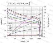
Here is the graph (x axis is current in A while y axis it potential in volts) :
View attachment 2

so the slope of -0.0209 corresponds to -r .
That means r = 0.0209 Ohms or 20.9 milliOhms.

So in conclusion, the DC internal resistance of my april 2015 Sony UR18650 VTC4 cell is 20.9 milliOhms at 23°C and 80-85% State of Charge (3.96V). Not too shabby :wink: This is totally consistant with previous results obtained here with some new VTC4 : https://endless-sphere.com/forums/viewtopic.php?f=14&t=73701#p1112249 (see point 4. the 6th graphic shown). Cells from DoctorBass are very affordable and seem to be as good as new, judging from my capacity testings and this DCIR preliminary testing !... (I know doctorbass stores them in a cool place around 10-15°C and not fully charged)...


With ideal conections, my future battery builds will have quite low resistance. I have 290 scavenged cells. Will test them all and make 3 battery pack (14S) that I'll use with a BBSHD mid drive I have (max 30A controller).
Pack #1 (14S10P) will be for long rides and to have fun with some WOT action and speed runs :twisted: !.... So in theory, 23.8 milliOhms which means 0.7V sag under full load at 30Amps.
Pack #2 (14S6P) will be for some mid lenght trips... Not so heavy at 3.8 kg. Will be 49 milliOhms, so 1.5V sag under full load at 30 Amps (I plan to use it at less that 30 amps). 8)
Pack #3 (14S4P) will be for short commutes (12-14 km roundtrip) in town... To be used with gentle throttle or PAS. Goal on this pack is range... not to flug it WOT all the time (probably cruising at 5-7 amp with 15-20Amps peaks at accelerations). With theoretical DCIR of 73.5 milliohm, that small 2.8 kg pack will sag by 2.2V at full 30 amp load (but i dont want to push it that hard) :mrgreen:

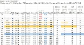
Here's my breakdown :
Sans titre-3.jpgSans titre-1.jpg

...Tired of being an eBike amateur... So I'm starting to use my brain more and do calculations :mrgreen:

Matador
 
Found a supplier for simple LTO bms. 10s-32s possibly more.
As you may know I've been playing with LTO for the last year. Until now low cost bms options have been elusive.
Two versions of high end 8s-24s lcd programmable are available, but over $200 each.
These should be from $75 -$150.
I will be getting some 20s 80a lto versions that I hope come in about $100 with shipping.
Pm me if anyone wants to get in on initial order. Ask Steve about LTO. He will be getting some I believe.
May also get a few 32s for 72v Gem cars.
 
Matador said:
I recieved my set of resistors by the mail today and made some preliminary testings. They are rated for 5% precision and 50W power... For me, it's perfect as the lowest value resistor (0,5 Ohm) shows less than 7A when placed on each of my cells which drops about 0.15 V (so about 7Watts..). Worst cell I tested (a totally dead on arrival cell (extremely rare in Makita Packs from my experience), salvaged at 0.03V, experimentally soldered on its positive teminal and charged to 4.20V.... With a horrible 1923 mAh instead of 2100.....) dropped 0.31 V, so it's still safe with that 50W resistor (about 14-15 Watts).

I took one of my good Sony VTC4 (date code on it is 2015 april) and tested it :

RESISTOR ............... Volts ............ Amps

0.5 Ohm ................3.818 V ............ 6.67 A
1.0 Ohms ...............3.876 V............. 3.68 A
2.0 Ohms ...............3.915 V..............1,91 A
2.2 Ohms................3.920 V..............1.76 A
4.0 Ohms ...............3.938 V..............0.98 A
None (float)............3.964 V..............0 A (measured before the 0.5 Ohm resistor measure... the external resistance is that of the multimeter which is astronomically high... meaning that the current is neglectible)

NB : Amp measures are taken all on the same scale (my meter is NOT an auto-scaling multimeter, so I dont have the problem of a mutimeter that changes from calibration shunt to calibration shunt... causing some break in the graph slope)

I have to be really fast with the 0.5 Ohm resistor, otherwise I end up discharging the cell to much. Hence, this is the first measure I do in order to avoid biasing the next measure. If I'd do the 0.5 Ohm measure at a moment other than being the first measure, it would overestimate the cell resistor by 20-25% more. The 1.0 Ohm can also be a problem if I'm not fast enough to take measure. 2, 2.2 and 4 Ohms are no problem as the voltage goes back to identical float voltage after pulling.

I then plotted the data on a graph where Amps are on abciss (x) and Volts are on ordinate (y)... I get a slop in the form of y = mx + b that translates into

V = -r I + E

where V is voltage
r is the internal resistance of cell
E = electromotrice force (which corresponds to float voltage with no current, here it is around 3.96V)
(for more teaching on this mathematical relationship/equation, see this vid : https://www.youtube.com/watch?v=Uz4X8i9ubeA)

Here is the graph (x axis is current in A while y axis it potential in volts) :
View attachment 2

so the slope of -0.0209 corresponds to -r .
That means r = 0.0209 Ohms or 20.9 milliOhms.

So in conclusion, the DC internal resistance of my april 2015 Sony UR18650 VTC4 cell is 20.9 milliOhms at 23°C and 80-85% State of Charge (3.96V). Not too shabby :wink: This is totally consistant with previous results obtained here with some new VTC4 : https://endless-sphere.com/forums/viewtopic.php?f=14&t=73701#p1112249 (see point 4. the 6th graphic shown). Cells from DoctorBass are very affordable and seem to be as good as new, judging from my capacity testings and this DCIR preliminary testing !... (I know doctorbass stores them in a cool place around 10-15°C and not fully charged)...


With ideal conections, my future battery builds will have quite low resistance. I have 290 scavenged cells. Will test them all and make 3 battery pack (14S) that I'll use with a BBSHD mid drive I have (max 30A controller).
Pack #1 (14S10P) will be for long rides and to have fun with some WOT action and speed runs :twisted: !.... So in theory, 23.8 milliOhms which means 0.7V sag under full load at 30Amps.
Pack #2 (14S6P) will be for some mid lenght trips... Not so heavy at 3.8 kg. Will be 49 milliOhms, so 1.5V sag under full load at 30 Amps (I plan to use it at less that 30 amps). 8)
Pack #3 (14S4P) will be for short commutes (12-14 km roundtrip) in town... To be used with gentle throttle or PAS. Goal on this pack is range... not to flug it WOT all the time (probably cruising at 5-7 amp with 15-20Amps peaks at accelerations). With theoretical DCIR of 73.5 milliohm, that small 2.8 kg pack will sag by 2.2V at full 30 amp load (but i dont want to push it that hard) :mrgreen:

Here's my breakdown :
View attachment 1

...Tired of being an eBike amateur... So I'm starting to use my brain more and do calculations :mrgreen:

Matador

I think we'll soon have a new to for this kind of work... the Battery Grinspector from Justin :
[youtube]qFSfx5Pf6GE[/youtube]
If I understand well you can check DCIR throug the whole spectrum of SOC ????
A bit like a did here : 5 current levels I used (5 different resistors), but not for a static voltage but for the whole voltage curves ????
IF it does that, I'm buying.
 
Meanwhile, I'm still waiting for my resistors on "expedited" shipping (due Monday last week). No news to report, except that now that every cell was tested, none are below 31ah and none are above 3mOhm.
 
Sunder said:
Meanwhile, I'm still waiting for my resistors on "expedited" shipping (due Monday last week). No news to report, except that now that every cell was tested, none are below 31ah and none are above 3mOhm.

Have you finally got them ?
 
Yes, but I've been too busy with work and life to even post here, let alone do any testing.

I am considering getting another 48 of these to upgrade my electric motorcycle.
 
Used them, abused them (overcharged to 5v, undercharged to 0.0v, sat in 60*C shed, went below zero, ) they are still going strong.

There are "rumours" that some of these are factory seconds, but I actually think thats its true, and good. You can get the same 66160s in 40, 30 and 25Ah variants. The 40Ah variants are priced as you would expect. The 30 and 25Ah variants are the surprisingly cheap ones.

I think that explains why almost all my 30Ah ones were 31-35Ah. They're all factory seconds from the 40Ah runs. 1/3rd of the cost, to lose 1/5th of the capacity? Count me in.
 
Back
Top