
You are using an out of date browser. It may not display this or other websites correctly.
You should upgrade or use an alternative browser.
You should upgrade or use an alternative browser.
ULtra Compact 1800W charger + Eltek programming
- Thread starter Doctorbass
- Start date
Dimensions are in the spec sheets.
Maybe Smartpack as an optional addon, just put threaded holes (rivnut) to allow choice of side vs top attachment?
Ability to mount in a stock Pelican-clone case for portability and weatherproofing would be nice.
Maybe Smartpack as an optional addon, just put threaded holes (rivnut) to allow choice of side vs top attachment?
Ability to mount in a stock Pelican-clone case for portability and weatherproofing would be nice.
J_haggerty
100 mW
- Joined
- Dec 4, 2018
- Messages
- 43
Yup that’s the c13/c14 standard. I’m running a similar port but specd for 20 amps and a panel mount snap in rather than bolts. Easy removal and replaceable nearly anywhere. If I can figure out how to upload a photo through my phone later I will.
Hi,
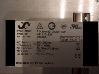
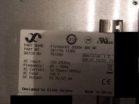
I found a source of some Flatpack2, Revision 1.2 / FW 1.10 / 1.10
All of these 9 can't be programmed for the fix start voltage.
But I also have a Revision 3.3 / FW 1.12 / 1.14.
This one can be programmed.
Does anyone think we can read out the Firmware of the 3.3 and flash it to the 1.2?
I found a source of some Flatpack2, Revision 1.2 / FW 1.10 / 1.10
All of these 9 can't be programmed for the fix start voltage.
But I also have a Revision 3.3 / FW 1.12 / 1.14.
This one can be programmed.
Does anyone think we can read out the Firmware of the 3.3 and flash it to the 1.2?
Attachments
Post to Imgur, helper apps abound.J_haggerty said:If I can figure out how to upload a photo through my phone later I will.
Then link from your posts, per photo, or to a gallery.
Google Drive similar but not conducive to privacy if you haven't let go of that fantasy yet.
J_haggerty
100 mW
- Joined
- Dec 4, 2018
- Messages
- 43
Has anyone used CAN to program two of these at once? I'd like to program the bottom half of my 2s2p stack using one arduino/CAN shield pair and the top half with another pair, but I don't know how to use CAN appropriately to communicate with multiple chargers and can't easily find other people's posts on the topic.
multifrag
100 W
I'm having trouble with reading CAN data after plugging in my battery. The charger stops sending CAN data in CV state. When battery charging switches to CC the data starts appearing. Electrically everything works, but I can't display the data on the screen for the CV period.
dakoal said:Hi,
I found a source of some Flatpack2, Revision 1.2 / FW 1.10 / 1.10
All of these 9 can't be programmed for the fix start voltage.
But I also have a Revision 3.3 / FW 1.12 / 1.14.
This one can be programmed.
Does anyone think we can read out the Firmware of the 3.3 and flash it to the 1.2?
Hey Buddy.
Seems I may have a single 2000W HE unit the same as you, won't respond to the fixed voltage setting, but will respond to Remi's original code and change voltage as long as you stay logged in.
Has anyone had this same issue and found a fix?
Cheers.
Ian
J_haggerty
100 mW
- Joined
- Dec 4, 2018
- Messages
- 43
Haven’t found a fix for that but I wanted to update on the charger housing. I reprinted with nylon and made a few modifications to inlets and outlets. It now has a deutsch 4 pin connector for CAN and direct cable inlet for higher gauge wire and higher safe charging amps.
I’m currently testing at 33 amps using two 110V flatpack2’s in parallel that I graciously got from a fellow former forum member.
I’m using these in conjunction with the ANT SmartBMs that I found out about from this forum to safely cut off charging in case of single cell overvoltage. It was cheap and works very well.
J_haggerty
100 mW
- Joined
- Dec 4, 2018
- Messages
- 43
Hi folks,
I've taken Remmie's code and modified it to make it a little easier to change the default voltage of most of these chargers. It has worked well for both my 1800W Flatpack 2's and my 110-120V 2000W HE Flatpack 2's. It doesn't currently incorporate the display code, so you still have to use a multimeter or the other code with a display to verify voltage, but it does do automatic serial number recognition.
I've taken Remmie's code and modified it to make it a little easier to change the default voltage of most of these chargers. It has worked well for both my 1800W Flatpack 2's and my 110-120V 2000W HE Flatpack 2's. It doesn't currently incorporate the display code, so you still have to use a multimeter or the other code with a display to verify voltage, but it does do automatic serial number recognition.
Code:
/* unsigned char login[8] = {0x14, 0x14, 0x71, 0x11, 0x08, 0x20, 0x00, 0x00};     //this is the serial number of the unit + 2 added bytes of 00 each, sernr on the unit reads 141471110820)
  CAN.sendMsgBuf(0x05005804, 1, 8, login);                                       //send message to log in and assign ID=1 (last 04 means ID=1, for ID=2 use 05004808 )

  unsigned char setdefaultvolt[5] = {0x29, 0x15, 0x00, 0x80, 0x16};              //this is the command for setting the default output voltage (Last two bytes, LSB first). 16 80 is the maximum voltage of 57.6 V
  CAN.sendMsgBuf(0x05019C00, 1, 5, setdefaultvolt);                             //send message to set ouput voltage to all chargers connected to the CAN-bus */
#include <mcp_can.h>
#include <mcp_can_dfs.h>
#include <SPI.h>
word defaultvoltage =9550; //11550;                                                         // set default voltage (divide by 100) (may not need both default and output)
//word outputvoltage = 4350;                                                         // set output voltage to (divide by 100)
word maxcurrent = 50;                                                              // set initial maxcurrent to 12.5A output
word overvoltage = 11750;
const int SPI_CS_PIN = 17;                                                          // Set CS pin to pin 10 (could be 9 for other CANshields)
unsigned char len = 0;
unsigned char serialnr[8];
unsigned char buf[8] ;
int msgreceived;
bool longwalkin = HIGH;                                                         //Choose HIGH for 60 second walkin and LOW for 5 second
long walkin = 0x05FF4005;
MCP_CAN CAN(SPI_CS_PIN);                                                            // Set CS pin for CANBUS shield

void setup()                                                                        // Initialisation routine
{ bool flag = LOW;                                                                  // set flag to low
  if (longwalkin == LOW)
  {
    walkin = 0x05FF4004;
  }
START_INIT:

  if (CAN_OK == CAN.begin(CAN_125KBPS))                                           // init can bus : baudrate = 125k !!
  {
  }
  else
  {
    delay(100);
    goto START_INIT;
  }

  //This next section sends one initial message that should set the default voltage.
  while (flag == LOW)                                                                  // cycle through until correct Canid allows message transmission
  {
    if (CAN_MSGAVAIL == CAN.checkReceive())                                             // check if data coming
    {
      CAN.readMsgBuf(&len, buf);                                                    // read data,  len: data length, buf: data buf
      INT32U canId = CAN.getCanId();                                                // read the CAN Id


      if (canId == 0x05014400)                                                          //this is the request from the Flatpack rectifier during walk-in (start-up) or normal operation when no log-in response has been received for a while
      {
        for (int i = 0; i < 8; i++)
        {
          serialnr[i] = buf[i];                                                        // transfer the message buffer to the serial number variable
        }
        CAN.sendMsgBuf(0x05004805, 1, 8, serialnr);                                  //send message to log in (DO NOT ASSIGN AN ID use 00) use 4805 for 60 second walkin and 4804 for 5 second
        msgreceived++;                                                               // increase the variable "msgreceived"
        unsigned char setdefaultvolt[5] = { 0x29, 0x15, 0x00, lowByte(defaultvoltage), highByte(defaultvoltage)};   //this is the command for setting the default output voltage (Last two bytes, LSB first). qnd long walk-in 4005 or short walk in 4004
        CAN.sendMsgBuf(0x05019C00, 1, 5, setdefaultvolt);                                                                     //(last 4 in header is for 5 sec walkin, 5 is for 60 second walkin)                                                                     //(last 4 in header is for 5 sec walkin, 5 is for 60 second walkin)
        flag = HIGH;
      }                                                                              // set flag to say that message has been sent
      else delay(100);
    }
  }
}

void loop()                                                                        // main program (LOOP)
{ delay( 20000);
  if (CAN_MSGAVAIL == CAN.checkReceive())                                             // check if data coming
  {
    CAN.readMsgBuf(&len, buf);                                                    // read data,  len: data length, buf: data buf
    INT32U canId = CAN.getCanId();                                                // read the CAN Id


    if (canId == 0x05014400)                                                          //this is the request from the Flatpack rectifier during walk-in (start-up) or normal operation when no log-in response has been received for a while
    {
      for (int i = 0; i < 8; i++)
      {
        serialnr[i] = buf[i];                                                        // transfer the message buffer to the serial number variable
      }
      CAN.sendMsgBuf(0x05004805, 1, 8, serialnr);                                  //send message to log in (DO NOT ASSIGN AN ID use 00) use 4805 for 60 second walkin and 4804 for 5 second
      msgreceived++;                                                               // increase the variable "msgreceived"
      unsigned char stmp7[8] = {lowByte(maxcurrent), highByte(maxcurrent), lowByte(defaultvoltage), highByte(defaultvoltage), lowByte(defaultvoltage), highByte(defaultvoltage), lowByte(overvoltage), highByte(overvoltage)};    // set rectifier to maxcurrent 57,0V (16 44) and OVP to 59.5V (17 3E) qnd long walk-in 4005 or short walk in 4004
      CAN.sendMsgBuf(walkin, 1, 8, stmp7);
    }                                                                              // nothing to do :)
  }
}
/*********************************************************************************************************
  END FILE
  Voltage settings
  80 16 => 1680 HEX = 57,60 Volt (= highest possible voltage
  E6 14 => 14E6 HEX = 53,50 Volt (= factory set voltage)
  FE 10 => 10FE HEX = 43,50 Volt (= lowest possible voltage)
*********************************************************************************************************/J_haggerty
100 mW
- Joined
- Dec 4, 2018
- Messages
- 43
Hey Camon
You get really lucky. Lol. There is a thread about it on electricmotorcycle.com by Dr Bass and I happened to message one of the people that posted there that lived in my area who had sold his Zero and he gave three of them to me. A very nice guy. It solves some of the issue that you normally see of not being able to take the full change in voltage of the battery from full to empty with a stack of two 57V units.
That’s the main benefit, as it would actually be more powerful to use two 57V 3000W HE’s stacked in series, but you wouldn’t be able to current limit them fully on my pack. Additionally, having the two 110v units in parallel reduces the amperage through each PCB. Since the PCBs I had made are probably best used at or below 35 Amps or so.
I’m planning to upload my CAD files for the charger housing. I won’t be uploading the PCB files yet, because I still have around 25 of them for the Flatpack2's and would like to sell off some of the extras before making the files public. Anyone is welcome to duplicate them if they can, but it’s probably as cheap and quicker to buy them from me if you plan to use my charger housing design.
J_haggerty
100 mW
- Joined
- Dec 4, 2018
- Messages
- 43
What would be really cool is if someone found a CANbus for Arduino that had isolated CAN inputs. Then you could current limit from 98V-115V—ideal for people with, say, 14 Nissan Leaf modules in series on their motorcycles...
Hi, everybody.. I've been away for a while on this thread and read now the messages. Is it true you guys want to contol sets of 2 Eltek's with their output in series with a partly isolated CANbus system and one Arduino to control these?
I've been strungling with this for a while and now I have developped a solution myself becouse I could't find a working Arduino shield for sale. I make now these PCB's for chargers for Zero owners who want to have a bunch of various Elteks on their bikes and charge way faster than the manufacture solution.
The pcb has also a hardware interface to read out the pilot signal from a charging station, so it can automatically dial up or down the charger pack due to the received Pilot signal. It is fully J1772 compatible.
It features a Leonardo Arduino, a straight Canbus connector (connected to the Eltek wich refers to minus of the DC side) and a isolated Canbus connector (connected to the Eltek wich refers to the positive side of the DC side), all designed to use together on one Arduino.
I've created up to a "octapack" with 8 Elteks stacked together and all being controlled with one Arduino!
Power can be obtained from various sources, the pcb is prepaired to house a few different DCDC or ACDC converters, depending on the useage. So power can come from the DC side of the batterypack 115V or a ACDC converter to use main power or use a logic 5V or 12V system.
New pcb's are currently in the making, but Corona is slowing things down. Please pm me If I can help anyone.
I got a flatpack2 2000w some years ago and i want to finally use it. The problem the last time i wanted to use it it keeps just clicking like a car turn indicator relais.
I am going to disassemble it but wondered if this behavour is known and what could cause it. There is no output voltage at all and on the front the leds also blink every falling or rising relais contact click.
I have revision 2.3 and i hope it is not dead as it should be new after all i know.
I am going to disassemble it but wondered if this behavour is known and what could cause it. There is no output voltage at all and on the front the leds also blink every falling or rising relais contact click.
I have revision 2.3 and i hope it is not dead as it should be new after all i know.
Darren2018
100 W
- Joined
- Aug 18, 2018
- Messages
- 223
Is this of any use to anyone? Seems like you guys do this for free but it might be useful if you want something a bit more simple.

https://vk4ghz.com/product/eltek-flatpack-2-controller/
https://vk4ghz.com/product/eltek-flatpack-2-controller/
Manny
10 W
I have 4 "FLATPACK2 48/3000HE G2" | Revision: 2.3 | SW: 1.01/2.01
using the arduino code i am able to set the default voltage and change the voltage and current on the fly.
when the power supply is in CC mode it works but only to a minimum voltage of 47V.
if I increase the load the voltage remains at 47V and the current will increase to keep the voltage up.
did anyone else see the? and is there a "fix" if it did this at 43.2V it is useble for me.
thanks for all the info
ridethelightning
1 MW
- Joined
- Jul 21, 2013
- Messages
- 2,010
subscribe
ridethelightning
1 MW
- Joined
- Jul 21, 2013
- Messages
- 2,010
Darren2018 said:Is this of any use to anyone? Seems like you guys do this for free but it might be useful if you want something a bit more simple.
DSC7370_900.jpg
https://vk4ghz.com/product/eltek-flatpack-2-controller/
ok so i ordered one of these to program a few flatpacks. they discontinued the 48v model, now the new one works for both 48 and 24v flatpacks. apparently some of the version 1 flatpacks have different protocol and are not compatible, only way is to use CAN with those.
Darren2018 said:Is this of any use to anyone? Seems like you guys do this for free but it might be useful if you want something a bit more simple.
DSC7370_900.jpg
https://vk4ghz.com/product/eltek-flatpack-2-controller/
Can anyone confirm they've had this work on a different version to what's listed on the site as compatible?
ridethelightning
1 MW
- Joined
- Jul 21, 2013
- Messages
- 2,010
yep worked with 2 different ones i have. apparently not good for sw 1
Hey Guys.
Hope you're all safe and well?
I am still using the Elteks where needed in my RC/UAV charge case builds and anotehr thank you to Remmie and the guys that made this possible.
The only problem has always been the need for Revision 3+ units ideally for me so that I can permeanantly set the output voltage and leave it at that, but now my electronics wizard has gont involved again on something to compliment his excellnt power PCB design.
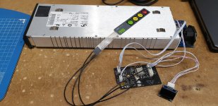
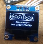
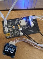
So I present to you the CANnedIce controller, this features an ESP-8266, Canbus controller, buck convter for upto 60 volts operation, I2C for OLED display output and a some other I/O pins we are going to expand with as time goes on.
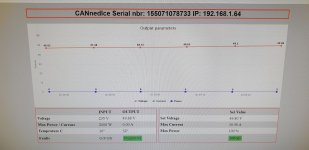
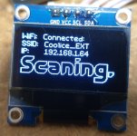
The ESP provides WiFi connectivity and can work as an access point for direct monitoring of the data coming out of the Eltek, or can be connected to a network for more remote monitoring. The designer has built in OTA updateability which is handy to.
Using the web interface the user can set a voltage output value, which is then updated regularly for pre-rev 3 units and then if the Eltek allows, the set voltage can be stored permeanantly.
Have some two button membrane switches coming which will neaten up the two required for reset and password reset.
Serial monitor within Arduino works and shows also.
I've only just got the first batch of 7 PCB's two days ago, so am still learning more as I go along, but I plan to make a video and upload it to YouTube for more information.
Not yet sat down and worked out a price yet, but it will be very competitive.
Ian Contessa
Hope you're all safe and well?
I am still using the Elteks where needed in my RC/UAV charge case builds and anotehr thank you to Remmie and the guys that made this possible.
The only problem has always been the need for Revision 3+ units ideally for me so that I can permeanantly set the output voltage and leave it at that, but now my electronics wizard has gont involved again on something to compliment his excellnt power PCB design.
So I present to you the CANnedIce controller, this features an ESP-8266, Canbus controller, buck convter for upto 60 volts operation, I2C for OLED display output and a some other I/O pins we are going to expand with as time goes on.
The ESP provides WiFi connectivity and can work as an access point for direct monitoring of the data coming out of the Eltek, or can be connected to a network for more remote monitoring. The designer has built in OTA updateability which is handy to.
Using the web interface the user can set a voltage output value, which is then updated regularly for pre-rev 3 units and then if the Eltek allows, the set voltage can be stored permeanantly.
Have some two button membrane switches coming which will neaten up the two required for reset and password reset.
Serial monitor within Arduino works and shows also.
I've only just got the first batch of 7 PCB's two days ago, so am still learning more as I go along, but I plan to make a video and upload it to YouTube for more information.
Not yet sat down and worked out a price yet, but it will be very competitive.
Ian Contessa
Attachments
john61ct said:WOW WOW WOW
Please strive to keep these available in stock for purchase
Charging enough to make that work sustainable for those involved
Sorry for the slow reply, I don't seem to get email prompts on posts.
Thanks for the compliment buddy, it's appreciated. I have a very knowledgable electronics expert who does amazing things for me and this controller being one of them.
Currently I have 7 of these controllers in stock, with another 8 on the way. One I am keeping leaving 6 to sell and I now have a small contactor control board coming also. What this will allow me to do is control the main DC output of the Eltek until it has had chance to settle to the required voltage for the equipment it's connected to.
As an example for my needs this allows me to use pre-Rev3 units on my RC/UAV LiPo chargers, but the chargers won't turn on until the voltage has hand chance to change to the set 48.9 volts, as they can only take a max of 50 volts, then this controller switches the contactor coil and power is applied.
I have two 60 amp contactors on the way from China to test this once these small additional PCB's arrive.
Ian Contessa
Similar threads
- Replies
- 66
- Views
- 29,625